
|
|
#3176
 03-15-2024, 03:35 PM
|
|||
|
|||
|
Quote:

|
|
#3177
03-19-2024, 10:22 AM
|
|||
|
|||
|
I'm posting the material for building my lrl for a new forum member.
|
|
#3178
03-21-2024, 07:45 AM
|
|||
|
|||
|
Quote:
|
|
#3180
04-08-2024, 09:12 AM
|
|||
|
|||
|
Quote:
|
|
#3181
04-08-2024, 01:56 PM
|
|||
|
|||
|
Quote:
Which version works well? What is a schematic? Give me the schematic Thank you for your love
|
|
#3182
04-08-2024, 02:31 PM
|
|||
|
|||
|
Quote:
|
|
#3183
04-08-2024, 02:34 PM
|
|||
|
|||
|
Quote:
Thank you
|
|
#3184
04-09-2024, 07:33 PM
|
|||
|
|||
|
Quote:
|
|
#3185
04-11-2024, 11:04 AM
|
|||
|
|||
|
Quote:
|
|
#3186
04-11-2024, 02:11 PM
|
|||
|
|||
|
Quote:
The 20 Mhz sensor stage is essentially the same as the 8 Mhz version, there are some more adjustments but this makes setup easier, I think you can use the 20 Mhz instead of the 8 Mhz.
|
|
#3187
04-11-2024, 04:00 PM
|
|||
|
|||
|
Quote:
|
|
#3188
04-24-2024, 10:28 AM
|
|||
|
|||
|
Quote:
I completed the assembly of the 8mhz crystal version, but I could not operate it. The measurements I took with the crystal are as follows. Can you help me please. TR1=B:8,0v E:9,2v C:15,6v TR2=B:0,2v E:0v C:5,8v TR3=B:0,8v E:2v C:7v TR4=B:2,4v E:1,8v C:7,6v TR5=B:0v E:0v C:16v 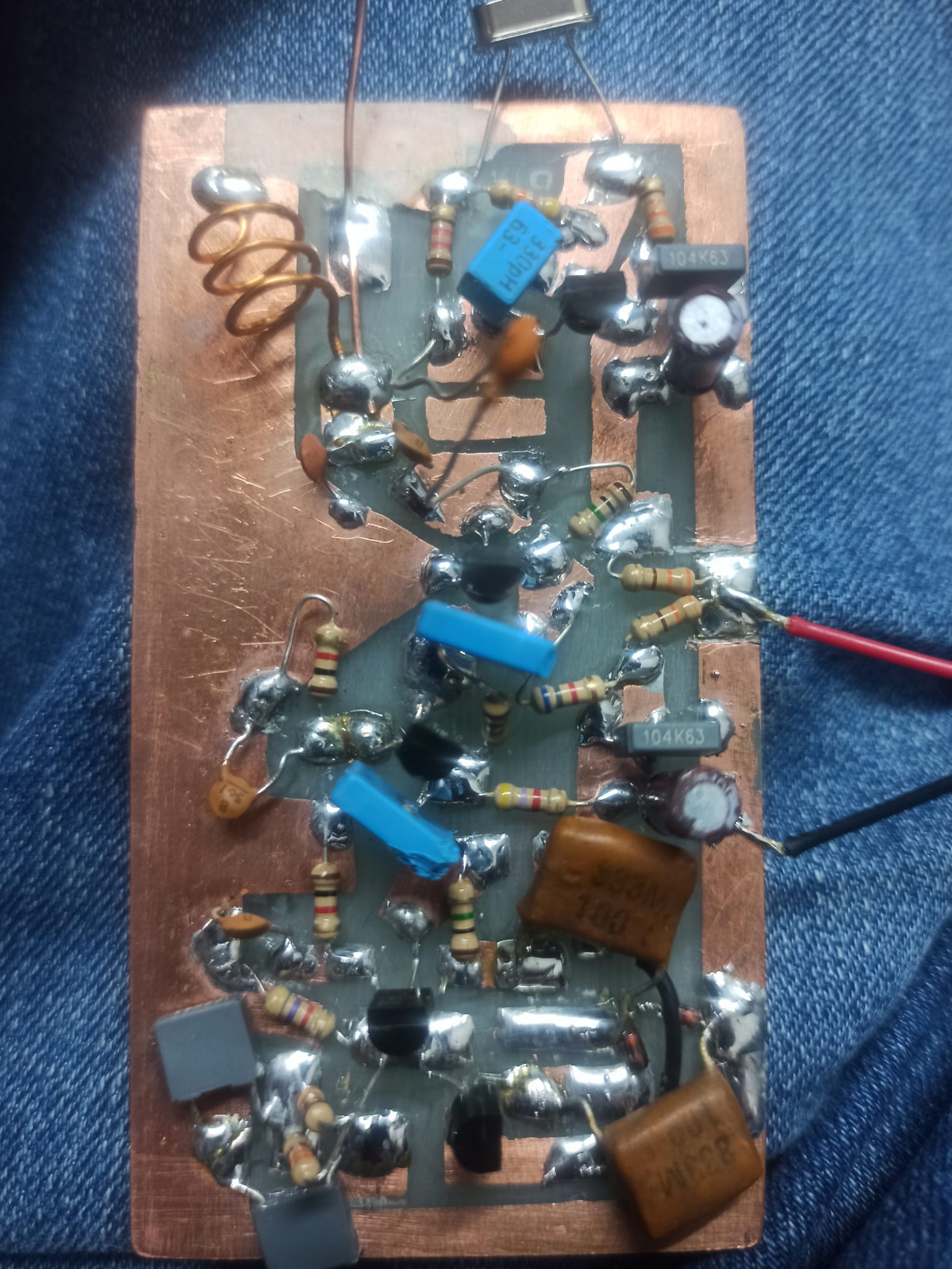
|
|
#3189
04-24-2024, 02:13 PM
|
|||
|
|||
|
My lrl is composed of the sensor stage + the display stage which also provides the stabilized 12V voltage, I attach the version with a LED which also includes the stabilizing part.
|
 |
|
|


 Linear Mode

