Announcement

Collapse
No announcement yet.

70kHZ transmitter

Collapse
X
 
  • Filter
  • Time
  • Show
Clear All
new posts

  • 70kHZ transmitter

    If one need a 70kHz transmitter with exact frequency, I suggest this solution:

    1.
    Use this module from eBay ($38 + free shipping):

    0.01- 5MHz DDS Function Signal Generator Module


    2.

    Signal generator has enough amplitude to act as transmitter you need, but if you insist that you need more power, then connect signal generator to this module from eBay:

    Mono 25W Audio Amplifier Module Board, Based on LM1875
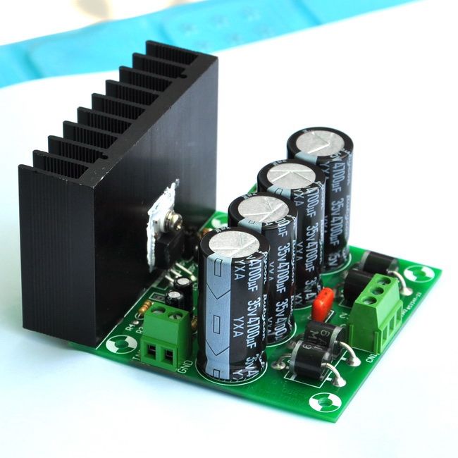


    Do not drive it with full power - 1/10 of max power, no more.

    Inductance of antenna (ferrite core or air core - the last one is better) have to be about 50mH. Exact value depend of antenna windings stray capacitance. You need to connect antenna instead of loudspeaker.

    Of course this transmitter can generate any other arbitrary frequency too (for some very different antenna inductance need to be recalculated).

    Use sine wave.
    Attached Files
    Global capital is ruining your life?
    You have right to self-defence!

  • #2
    tank you very much freind
    I have a problem in calculating the period number and size of the ferrite coil.Get tips on how to calculate the winding.If there is a formula to give.
    If I have a signal generator, and can help to strengthen the ferrite Can I send a wave?
    How?
    tanks
    ubram
    Knowledge is the greatest wealth

    Comment


    • #3
      Originally posted by mustefa ubram View Post
      tank you very much freind
      I have a problem in calculating the period number and size of the ferrite coil.Get tips on how to calculate the winding.If there is a formula to give.
      If I have a signal generator, and can help to strengthen the ferrite Can I send a wave?
      How?
      tanks
      ubram
      It is simple, if you have L-meter (inductance meter).

      You need to wind 10 (or better 20 or 30) testing turns of wire (diameter about 0.3 or so) on ferrite rod antenna you have.

      Then measure inductance.

      Par example:

      If you wound 30 testing turns and then measured inductance is 15mH, then you calculate total turns this way:

      30 / 15 = 2

      This mean that you need 2 of turns to get 1mH.

      To get 50mH you need 50x2(turns)=100 (turns).

      So you need 100 turns in total on your ferrite rod to get 50mH ferrite cored antenna.


      Ferrite cored transmitter antenna is not the best solution for TX, air cored antenna is better. Of course it depend of what you need and what you try to build. If you need "shielded" (i.e. mounted in a tin can) antenna (to radiate in one direction) ferrite core antenna can be better solution than air core.
      Global capital is ruining your life?
      You have right to self-defence!

      Comment


      • #4
        Originally posted by WM6 View Post
        It is simple, if you have L-meter (inductance meter).

        You need to wind 10 (or better 20 or 30) testing turns of wire (diameter about 0.3 or so) on ferrite rod antenna you have.

        Then measure inductance.

        Par example:

        If you wound 30 testing turns and then measured inductance is 15mH, then you calculate total turns this way:

        30 / 15 = 2

        This mean that you need 2 of turns to get 1mH.

        To get 50mH you need 50x2(turns)=100 (turns).

        So you need 100 turns in total on your ferrite rod to get 50mH ferrite cored antenna.


        Ferrite cored transmitter antenna is not the best solution for TX, air cored antenna is better. Of course it depend of what you need and what you try to build. If you need "shielded" (i.e. mounted in a tin can) antenna (to radiate in one direction) ferrite core antenna can be better solution than air core.
        tank you very much dear freind
        Knowledge is the greatest wealth

        Comment


        • #5
          Here proposed TX configuration can be used till to 150kHz, even more. Of course not with same antenna specifications given here.

          For frequencies 70kHz +-10kHz antenna even do not need to be recalculated.
          Global capital is ruining your life?
          You have right to self-defence!

          Comment


          • #6
            Originally posted by WM6 View Post
            .
            Ferrite cored transmitter antenna is not the best solution for TX, air cored antenna is better. Of course it depend of what you need and what you try to build. If you need "shielded" (i.e. mounted in a tin can) antenna (to radiate in one direction) ferrite core antenna can be better solution than air core.
            dear wm6
            Is the ferrite core and reflector antennas can be directly sent 70kh frequency?
            Frequency of 70 kHz with a transmitter power is enhanced to within 50 meters sent?
            Changes in the frequency or electromagnetic radius of 50 meters on the ground with metal?in coil ANTENNA and ferrite core?
            Knowledge is the greatest wealth

            Comment


            • #7
              Originally posted by mustefa ubram View Post
              dear wm6
              Is the ferrite core and reflector antennas can be directly sent 70kh frequency?
              Frequency of 70 kHz with a transmitter power is enhanced to within 50 meters sent?
              Changes in the frequency or electromagnetic radius of 50 meters on the ground with metal?in coil ANTENNA and ferrite core?
              Sorry mustefa, my English is very bad. I do not understand your questions.
              Global capital is ruining your life?
              You have right to self-defence!

              Comment


              • #8
                Hello Barbarossa, this can be your solution. First use signal generator to check your GG receiver exact frequency, then use the same to build TX stage working at the same frequency. Use round or square antenna so you can play with TX wave propagation (polarization) combined with proper TX distance.
                Global capital is ruining your life?
                You have right to self-defence!

                Comment


                • #9
                  Just a quick note. Those frequency generators are rejects. They did not pass the quality standards. You pays your money and you takes your chances.

                  Comment


                  • #10
                    Originally posted by Mike(Mont) View Post
                    Just a quick note. Those frequency generators are rejects. They did not pass the quality standards. You pays your money and you takes your chances.
                    Reject by NASA or MikeMontLab?

                    If you can find something better and more precise (look at data below) for $38, then please tell us:

                    Frequency range:0.01Hz ~5MHz(SG1005)
                    Resolution:0.01Hz
                    Frequency Stability:±1×10⁻⁶
                    Frequency accuracy:±5×10⁻⁶
                    Sine wave distortion:≤0.8% (reference frequency is 1kHz)
                    Global capital is ruining your life?
                    You have right to self-defence!

                    Comment


                    • #11
                      I speak from first hand experience, so yes I guess it is from Mike(Mont)'s lab.

                      Comment


                      • #12
                        Sorry, posted this on the wrong thread.

                        I'm not saying the chip is bad. It's the hardware/controls that is the weak link.

                        Comment


                        • #13
                          Hi WM6.
                          I need something like your schematic for an experiment to locate caves. I must use a wire 150 ... 200m as antenna and at the end it will be grounded. Have you any program to calculate the antenna resistance so to match it with the amplifier??

                          Regards
                          Geo

                          Comment


                          • #14
                            Originally posted by Geo View Post
                            Hi WM6.
                            I need something like your schematic for an experiment to locate caves. I must use a wire 150 ... 200m as antenna and at the end it will be grounded. Have you any program to calculate the antenna resistance so to match it with the amplifier??

                            Regards
                            Hi Geo,

                            You mean end of air cored coil antenna cold wire end connected to circuit ground (similar as on block schema in my first post but without ferrite core) or straight antenna wire end grounded in soil?

                            In second case (straight antenna wire end grounded in soil) there is no way to proper adapt resistance of 150m wire at VLF band to your amplifier output. But if you insist on this configuration, forget resistance and drive your amplifier at max 25% of its power. Another solution is to use (for <30khz band) an old speaker transformer (for 4-8 ohm speakers) connected in reverse to amplifier (Warning: high voltage at output!) and max. 50% of amp. power. For higher frequencies use ferrite transformer (if you build one on bigger ferrite toroid primary have to be 4 ohms and secondary windings at your wish - say 50Vpp to not be dangerous).

                            In first case (air cored coil antenna cold wire end connected to circuit ground) you chose antenna resistance according technical specification of amplifier you use, which is in amplifier from post above about 4 Ohms or a little more. You do not need special antenna tunning (SWR) as on HAM bands. Never drive your amplifier at more than 75% of max power.
                            Global capital is ruining your life?
                            You have right to self-defence!

                            Comment


                            • #15
                              Originally posted by WM6 View Post
                              Hi Geo,

                              You mean end of air cored coil antenna cold wire end connected to circuit ground (similar as on block schema in my first post but without ferrite core) or straight antenna wire end grounded in soil?

                              In second case (straight antenna wire end grounded in soil) there is no way to proper adapt resistance of 150m wire at VLF band to your amplifier output. But if you insist on this configuration, forget resistance and drive your amplifier at max 25% of its power. Another solution is to use (for <30khz band) an old speaker transformer (for 4-8 ohm speakers) connected in reverse to amplifier (Warning: high voltage at output!) and max. 50% of amp. power. For higher frequencies use ferrite transformer (if you build one on bigger ferrite toroid primary have to be 4 ohms and secondary windings at your wish - say 50Vpp to not be dangerous).

                              In first case (air cored coil antenna cold wire end connected to circuit ground) you chose antenna resistance according technical specification of amplifier you use, which is in amplifier from post above about 4 Ohms or a little more. You do not need special antenna tunning (SWR) as on HAM bands. Never drive your amplifier at more than 75% of max power.
                              Hi WM6. I am interesting for the second case. Frequency will be 100Khz so not so good for audio transformer. Ferrite core maybe is a solution!!!!. I want to have a strong signal at distance of 10...30m far from antenna so i believe that there is not need for high power.
                              2...3 watts maybe is enough

                              Regards
                              Geo

                              Comment

                              Working...
                              X