Announcement

Collapse
No announcement yet.

Lrl from Italy

Collapse
X
 
  • Filter
  • Time
  • Show
Clear All
new posts

  • Hi enjoykin4,
    I think that the lrl reveals all no ferrous metals but the maximum sensibility is for gold and silver. I found a brass cartridge at 1 meter distance and 2 cm buried.
    Best Regards

    Comment


    • Thank you Signore Franco !!

      Best Regards from Russia
      Enjoykin4

      Comment


      • Τhanxs Mr.Franco

        Comment


        • Signore Franco do you ready to open gold hunting season in Italy this 2016 (7524) year ??

          I hope your wife's health will be OK and you will find time for Gold prospecting !!

          Signore Franco in the present Russian article, are some ideas how to boost location distance and prospecting depth of your Quartz LRL (called on this forum Franco Phantom LRL) and also PLL4046 LRL using 2-Spiral coils (2S-Coils) antenna as a low impendance input part of your "Scalar detector". Keep in mind that 2S-Coils are sclara type coils (both working in opposite phase to each other) and how has demonstrated by researchers 2S-Coils field is localized in the near-field zone and the that filed has more uniform structure than the field of the conventional spiral coils(like is case of your 70 turns coil). Also 2S-Coils has higher sensitivity to sclara signals (read sensitivity to Gold and Silver) than the analogous conventional coils.

          A two-spiral flat coil for detecting 14N NQR signals
          ARTICLE from RUSSIAN PHYSICS JOURNAL · SEPTEMBER 2005

          Download free at


          Best regards
          Enjoykin4

          Comment


          • Hi enjoykin, thanks for link, but there is no data in publication, if coil should be driven by sine or square wave.

            Or it is no matter of wave shape?
            Global capital is ruining your life?
            You have right to self-defence!

            Comment


            • Hi enjoykin4,
              Unfortunately at the moment I do not know when I'll start the season for the gold, but I hope that many friends in the forum have luck. Thanks for the link to the article related to two flat spiral coil, but I'm just a hobbyist and not an engineer or a physicist, but I deal with electronic more than 50 years (I was 14). The particularity of my antenna coil is that the two ends are connected together and it would be interesting to study its features.
              Best Regards

              Comment


              • Hi WM6

                I think that no matter of wave shape !!

                Best regards
                enjoykin4

                Comment


                • Hi FrancoItaly

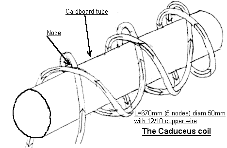
                  Yes of course. Also in my oppinion will be very interesting study Scalar Caduceus coil in your LRL


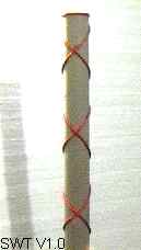
                  The coil is wound on a 45 degree angle up and down the length of the form creating a series of 90 degree intersections along the full lenght.


                  Best regards
                  enjoykin4

                  Comment


                  • Originally posted by enjoykin4 View Post
                    Hi FrancoItaly

                    Yes of course. Also in my oppinion will be very interesting study Scalar Caduceus coil in your LRL


                    The coil is wound on a 45 degree angle up and down the length of the form creating a series of 90 degree intersections along the full lenght.


                    Best regards
                    enjoykin4
                    Hi Mr FrancoItaly,
                    It's the first time i've been in this forum and i want to thank you in advance for the drawings and the right information you provide us.
                    Today i've managed to make the PCB from 8MHz sensor.
                    After i've done the tests you've written in this forum..especially the one where i had to put my hands near the antenna...it worked and the led turned on...i would like to know if all of the three leds need to turn on..or just one of them? how could i know that there's a coordination in P1 and P2? also..the out of sensor stage is 5,26 V.
                    thank you very much for your help!

                    Comment


                    • Originally posted by FrancoItaly View Post
                      Hi enjoykin4,
                      Unfortunately at the moment I do not know when I'll start the season for the gold, but I hope that many friends in the forum have luck. Thanks for the link to the article related to two flat spiral coil, but I'm just a hobbyist and not an engineer or a physicist, but I deal with electronic more than 50 years (I was 14). The particularity of my antenna coil is that the two ends are connected together and it would be interesting to study its features.
                      Best Regards
                      Hi Mr FrancoItaly,
                      It's the first time i've been in this forum and i want to thank you in advance for the drawings and the right information you provide us.
                      Today i've managed to make the PCB from 8MHz sensor.
                      After i've done the tests you've written in this forum..especially the one where i had to put my hands near the antenna...it worked and the led turned on...i would like to know if all of the three leds need to turn on..or just one of them? how could i know that there's a coordination in P1 and P2? also..the out of sensor stage is 5,26 V.
                      thank you very much for your help!

                      Comment


                      • Originally posted by FrancoItaly View Post
                        Hi enjoykin4,
                        Unfortunately at the moment I do not know when I'll start the season for the gold, but I hope that many friends in the forum have luck. Thanks for the link to the article related to two flat spiral coil, but I'm just a hobbyist and not an engineer or a physicist, but I deal with electronic more than 50 years (I was 14). The particularity of my antenna coil is that the two ends are connected together and it would be interesting to study its features.
                        Best Regards
                        Hi Mr FrancoItaly,
                        It's the first time i've been in this forum and i want to thank you in advance for the drawings and the right information you provide us.
                        Today i've managed to make the PCB from 8MHz sensor.
                        After i've done the tests you've written in this forum..especially the one where i had to put my hands near the antenna...it worked and the led turned on...i would like to know if all of the three leds need to turn on..or just one of them? how could i know that there's a coordination in P1 and P2? also..the out of sensor stage is 5,26 V.
                        thank you very much for your help!

                        Comment


                        • Hi KwstasXri,
                          P1 is used to adjust the threshold and P2 adjusts the gain, they are not independent, varying P2, P1 needs to be adjusted again. P2 can be adjusted once and for all. It is sufficient that turns on only one led but normally the LED turns off by touching the antenna. Usually touching the antenna at the output of sensor stage the signal goes low and with a good target
                          the signal augments, but I think that it's important that there is a signal change, negative or positive. It's also useful to shield the box where is the pcb.
                          Best Regards

                          Comment


                          • Originally posted by FrancoItaly View Post
                            Hi KwstasXri,
                            P1 is used to adjust the threshold and P2 adjusts the gain, they are not independent, varying P2, P1 needs to be adjusted again. P2 can be adjusted once and for all. It is sufficient that turns on only one led but normally the LED turns off by touching the antenna. Usually touching the antenna at the output of sensor stage the signal goes low and with a good target
                            the signal augments, but I think that it's important that there is a signal change, negative or positive. It's also useful to shield the box where is the pcb.
                            Best Regards
                            Mr FrancoItaly...thank very much!

                            Comment


                            • I think the lrl with 4046 work fine franko

                              Comment


                              • Hi taxma1981,
                                this test demonstrates that LRL works well in a closed environment, almost certainly it works outdoors. Naturally LRL is also sensitive to the electromagnetic signal sources that fall in the frequency range of the LRL.
                                Best Regards

                                Comment

                                Working...
                                X