My idea, my friend Franco, is as shown in the pictures below. An MP3 player can be used in the car as a transmitter by adjusting the capacity, although its energy is low, but it is ready and cheap. And good luck.
My idea, my friend Franco, is as shown in the pictures below. An MP3 player can be used in the car as a transmitter by adjusting the capacity, although its energy is low, but it is ready and cheap. And good luck.
I sincerely think that a dedicated, more versatile system would be better, also because it should be used together with the lrl, i.e. permanently connected to it.
[QUOTE=FrancoItaly;161971]It is possible, but the L/C resonant circuit is in the FM range and therefore the frequency of the external oscillator must be tuned to this frequency (or one of its harmonics).
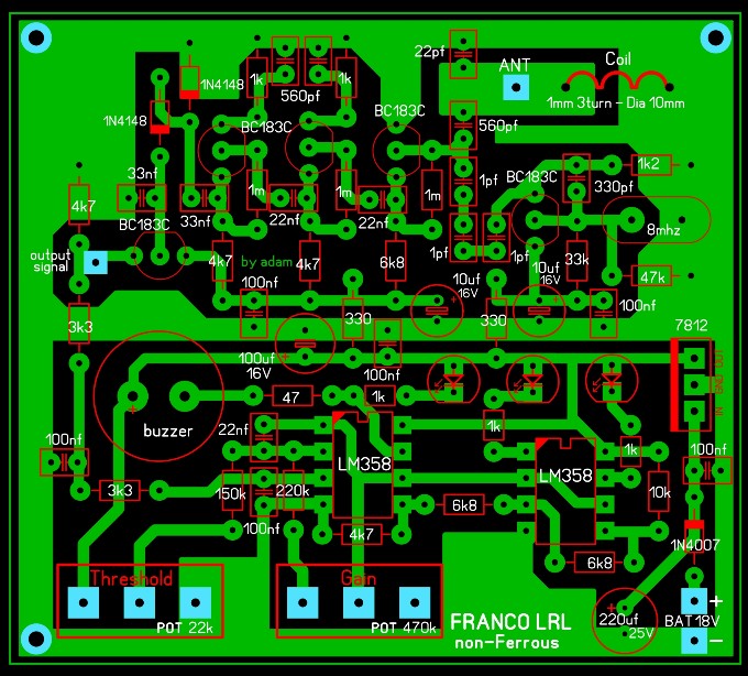
Omar on this board has one small mistake c16 33n must be based on Tr5
It is possible, but the L/C resonant circuit is in the FM range and therefore the frequency of the external oscillator must be tuned to this frequency (or one of its harmonics).
Omar on this board has one small mistake c16 33n must be based on Tr5
Pahom is right.
As Omar has installed C16, the circuit does not work.
Thanks Omar, due to my personally needs of container size and how I engineered my device, I had to rearrange and redesign the pcb's tracks. I had checked them one by one, but I hadn't noticed the error on c16. So that's the only mistake made, is everything else ok?
Thanks Omar, due to my personally needs of container size and how I engineered my device, I had to rearrange and redesign the pcb's tracks. I had checked them one by one, but I hadn't noticed the error on c16. So that's the only mistake made, is everything else ok?
My apologies to you, my friend, and to the others. Unfortunately, I did not check the drawing because the circuit is simple, but now I checked the drawing. There are no errors, it is only the location of the 33nF capacitor, and it has been corrected. And good luck
[QUOTE=omar;161992]My apologies to you, my friend, and to the others. Unfortunately, I did not check the drawing because the circuit is simple, but now I checked the drawing. There are no errors, it is only the location of the 33nF capacitor, and it has been corrected. And good luck[/QUOTOmar, everything is fine. For this, forums are created. To communicate, share, help whenever possible. The board is working, only as Franco recommended, it should be done on two-sided fiberglass. Then there is less fluctuation at the control point.
The pieces must be soldered immediately after cleaning the board, because the copper oxidizes quickly and the problem arises. And it must be ensured that the pieces are welded correctly, because weak welding means a weak connection or separation, and this fails the device to work. Transistors whose gain is not less than 450hfe should be used, such as BC183C, bc184c, or bc173c. For example, (BC547C is not suitable, as it will not achieve the required gains, and therefore the device has little sensitivity.) To increase the gain and extend the FM range you can use 2N7052 OR 2N7053. The device suffers from the need for frequent rebalancing like other conventional metal detectors.( What is not known is whether the full FM signal reaches the detection diode)
The pieces must be soldered immediately after cleaning the board, because the copper oxidizes quickly and the problem arises. And it must be ensured that the pieces are welded correctly, because weak welding means a weak connection or separation, and this fails the device to work. Transistors whose gain is not less than 450hfe should be used, such as BC183C, bc184c, or bc173c. For example, (BC547C is not suitable, as it will not achieve the required gains, and therefore the device has little sensitivity.) To increase the gain and extend the FM range you can use 2N7052 OR 2N7053. The device suffers from the need for frequent rebalancing like other conventional metal detectors.( What is not known is whether the full FM signal reaches the detection diode)
Thanks Omar! Cool transistors need to buy these !!!!
if the sensor stage auto oscillates it means that the amplification is sufficient, provided that the oscillation does not occur due to an unsuitable pcb.
If transistors with sufficient gain are not found, R10 and R12 can be decreased, for example 470 ohms.
The voltage drop of the diodes does not matter since the voltage changes are measured.
The FM signal is processed in mixer stage TR2 and is not amplified further.
My apologies to you, my friend, and to the others. Unfortunately, I did not check the drawing because the circuit is simple, but now I checked the drawing. There are no errors, it is only the location of the 33nF capacitor, and it has been corrected. And good luck
No problem Omar, indeed I personally thank you for posting your pcb, it served me a lot as a starting point for developing my circuit. The important thing is to collaborate, notice mistakes and correct them. We are human... I wanted to ask the more experienced ones, is the BC548C ok?
The bc547c / bc548c / bc549c transistors have a gain in the lower limits of 420hfe.
The circuit needs to adjust and reduce the value of the resistance R12 to achieve the required gain with it. As our friend Franco said.

 Tweet
Tweet


Comment