

 Tweet
Tweet
Originally posted by omar
View Post
-
I'm sorry Omar, but the 548C has hfe gain from 420 to 800, the ones I selected for my circuit, I tested them with a Chinese multi-tester and they all have hfe values above 500. Do you think it's too low? Better if I replace them or by intervening on the resistors, can I still get a good result? -
A gain of 500 is sufficient, by the way higher values are difficult to obtain.Originally posted by Inna View PostComment
-
Thanks mr. Franco, so if I change the values of r10 and r11 to 470 ohms, I can use the bc548cs, increasing the gain a bit.... Is that right?Originally posted by FrancoItaly View PostComment
-
Sorry, errata corrige: r10 and r 12...Comment
-
Originally posted by Inna View Post
Back up. Put in variable resistors to increase the gain when you need it. So as not to disassemble and install and damage the circuit. I know that the device must sense the magnetic north and the sky, then it is ready for field work.
Comment
-
note. Variable rectifiers are set only once. When the desired sensitivity is reached. Leave the third leg of the variable resistance in the air means not connected.
In the end, I extend my thanks and gratitude to our friend Franco for supporting the topic and helping the members.
https://top4top.io/downloadf-2561g1si50-rar.htmlComment
-
Well done. When you get the right gain value, if possible, you can replace the trimmers with fixed resistors with a value close to the value measured between the extreme pin and the central pin which are connected to the pcb.Comment
-
-
I made a modification of franco lrl this week, and I have very strange results ???
no reaction to electrical or magnetic interference, it only reacts to the white LED lamp, and the sound is very looklike to a magnetometer ??Comment
-
Help for Coil made.
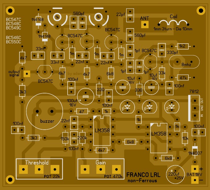
Please, can anyone tell me if this coil (L1) is correct? Is the number of turns right as seen in the picture? I add that the diameter is 1 cm, while the section of the wire is 0.7 mm. Do I necessarily have to use the 1 mm wire? Thank you.Attached FilesComment
-
-
The coil is perfect, however it is not critical.Comment
-
Good morning to everyone. Sorry if I ask questions that may have already been answered in the past. But I saw on a YouTube video that someone put a digital display voltmeter on this device. I wanted to know what its function could be and the difference, from the 3-leds monitor, and if it a good thing to mount on. And possibly where it should be connected. Maybe the (-) on ground and the (+) on TR5's emitter output? Thank you.Attached FilesComment
-
-
To be clear: in this point?Attached FilesComment
-
-
In my opinion 3 leds are sufficient, however a digital display voltmeter must be connected to the output of the first LM358 which is the DC amplifier stage.Comment
-
Good morning Mr. Franco, please could you tell me the right point to connect the display on first LM358?Originally posted by FrancoItaly View Post
Many thanks.Comment
Comment