

 Tweet
Tweet
Digital meter at IC1A output and ground. However, the stage relating to the buzzer and the first LED is necessary. I attach a display stage easier to adjust the threshold.
-
-
Because I made the last Omar's pcb, I should ask if It's the blue point in the attached scheme, the right point to connect the (+) positive input of the multimeter?Attached FilesComment
-
-
Yes it's correct.Comment
-
Hello, I would like to ask if it was possible to power this device with a single 9V battery and then a 12V regulated step-up module, thus eliminating the 7812. Has anyone already tried it? Could it work like this? Thanks.Comment
-
I do not recommend this solution, as these step-up modules work via an internal oscillator which could interfere with the sensor stage.Comment
-
Good advice. Thanks Mr. Franco.Comment
-
Hi Mr. Franco,
I'm talking to you because lately this forum seems to be little frequented. Too bad because it's so interesting, but I also understand that I'm the last to arrive and I missed the best...
I still have to finish building your LRL and for an inexperienced one like me, I already foresee many problems in the calibration.
However I'm always wondering if it was possible to improve the aspect concerning the power supply of the device and I asked and proposed if, in order not to affect the circuit, to be able to use a 12V, 1.2Ah lead battery + the step-up module or possibly a diode booster circuit, to raise the voltage to 16/18 Volt.
But this time, these elements will have to be released from the body of the LRL, ie distant and connected for example to the handle, through a simple cable.
Maybe it could improve stability and battery work time. Sorry if I ask many questions.
Thanks for your help, always in time.Comment
-
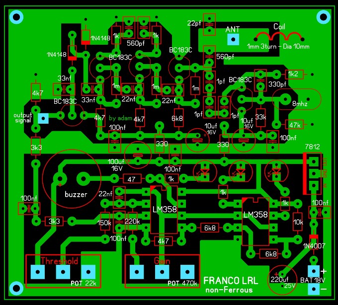
Yes, it's true, at the moment the forum is not very popular, but there are few topics to develop, however lrl from Italy has reached almost one million views, even in many years of activity. The lrl is not simple to implement, where there is a large amplification at relatively high frequencies there are always problems. The only pcb I made and made available is the sensor stage , and I recommended to use a double sided pcb, or shield the bottom with aluminum foil or another unetched pcb. The first lrl had no oscillator but simply self-oscillated, it was a bug detector that I found worked like the lrl. About power I recommend you again to use the original system with two 9V batteries, over all the consumption is about 20mA.Comment
-
Yes, Mr. Franco, I will leave the power supply as the original. I'm doing a very particular montage, I used a plastic container that covered a bottle of perfume. I will connect the handle to the negative on the outside, to have contact with the hands and I will put the batteries in the hollow handle. As for the pcb, I chose to process the last one posted by Omar and I've already shielded it with a sandwich made up of a layer of aluminum foil below and a layer of cardboard above, so it will be well insulated from contact with the pcb tracks. But the aluminum is also connected to the negative like the handle. I also built the antenna amplifier that was suggested separately, I provided the 40 pF variable capacitor (the only one value now I have) at the antenna input, so as I wrote, it won't be easy to calibrate everything, there are many variables. I'm afraid I have to ask for his help often. However for now I'm going ahead with the construction, when I can due to lack of time. Thank you.Comment
-
A person photographed and detected (iron grille) inside a concrete wall in infrared. It seems that metals, especially those with heavy atoms, are radioactive when they are under pressure.

If you photograph a large amount of gold, such as a goldsmith's shop, with a mobile camera, with the flash on. You will clearly see that gold sends low-frequency electromagnetic pulses in the form of circular packages. It is detected by photoinduction. The phenomenon, and God knows best, exists. But where is the right way? We do not know . ThanksComment
-
Hi Omar, about the picture above: it's an infrared or an ultraviolet photograph?Comment
-
-
Strange... I can download it.Comment
-
Sorry, I want to post the .rar file directly, but the system doesn't accept it and doesn't allow it to load, because the file is over 1 mb.Comment
-
I want to help you, click at the link and after on the points shown in the attached images.Attached FilesComment
-
Comment