

 Tweet
Tweet
For C2-C3-C3 I used the parasitic capacitance of the board. For C13-C14 (470pf). I use one printed circuit board for the whole lrl.
-
-
As I told you, a PCB just for the sensor stage, with the bottom face connected to ground, makes a higher gain possible.Originally posted by kiro077 View PostComment
-
If there are many electromagnetic disturbances inside the house it is better to calibrate outside, also remember that the antenna must be connected during these operations, I recommend extending it to about 40cm.Originally posted by FrancoItaly View PostComment
-
If I shield the box, will it get more amplification?Comment
-
it is possible, in fact the body participates in the detection process, holding it with two hands the gain increases compared to holding it with just one hand, furthermore the lrl remains less sensitive to disturbances, it must be shielded (with aluminium foil, including the handle).Originally posted by kiro077 View PostComment
-
Merhaba Omer, I disabled the diode. I made a direct connection. How should I correct the positions of the 33 nano capacities?Originally posted by omar View PostComment
-
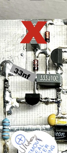
Comment
-
Both diodes are needed, they constitute a full wave rectifier, since silicon diodes have a conduction threshold of about 0.7V and signals lower than this threshold are blocked. However, this is not a problem since the signals are of higher amplitude.Originally posted by omar View PostComment
-
Omer, first of all, thank you. I corrected the mistake I made. I am operating it with DC 18V supply, the buzzer is constantly beeping. The adjustable resistor only lights up the first Yellow LED and then the Blue LED. The Green LED close to the 7812 Regulator does not light up at all. I need to pay a little more attention.Comment
-
-
Dear osman34
How is istanbul?
Probably you have problem with your second lm358
Since first LED works, you should have Signal at entrance leg3 of second lm358. But both leds are not works..seems problem is on lm358.
Maybe burned..or maybe miss connection..check solderimg.Comment
-
Hello Mr. Franko. I have a question about the settings of c13, c14 and c2-3-4. First we remove the crystal. Then we decrease the value of c13 until the emitter Tr3 oscillates. We increase the value of c13 a little and leave it like that and it does not oscillate. Do we also need to measure the emitter Tr4 for C14? After adjusting c13 and c14 we measure the emitter Tr5 and adjust the voltage from c234.Comment
-
All measurements are made on the TR5 emitter and are a continuous voltage. Increasing C13/C14 increases the gain, therefore the output voltage, to avoid self oscillation you must decrease C13/C14. C2/C3/C4 are only used to fix the output voltage to a correct value.Comment
-
This is where things get difficult. For example, does the value of c13 affect the value of c14? If so, how much we need to change c13 or 14 remains unclear.Originally posted by FrancoItaly View PostComment
-
You can change only C13 first, if the value (greater than 10nF) is not enough also increase C14. Otherwise (if acting on C13/C14 is not enough) vary R10/R12, decreasing the value increases the gain. R10/C13 and R12/C14 are two high pass filters. In a later version of the lrl I put two trimmers in place of R10/R12.Comment
Comment