

 Tweet
Tweet
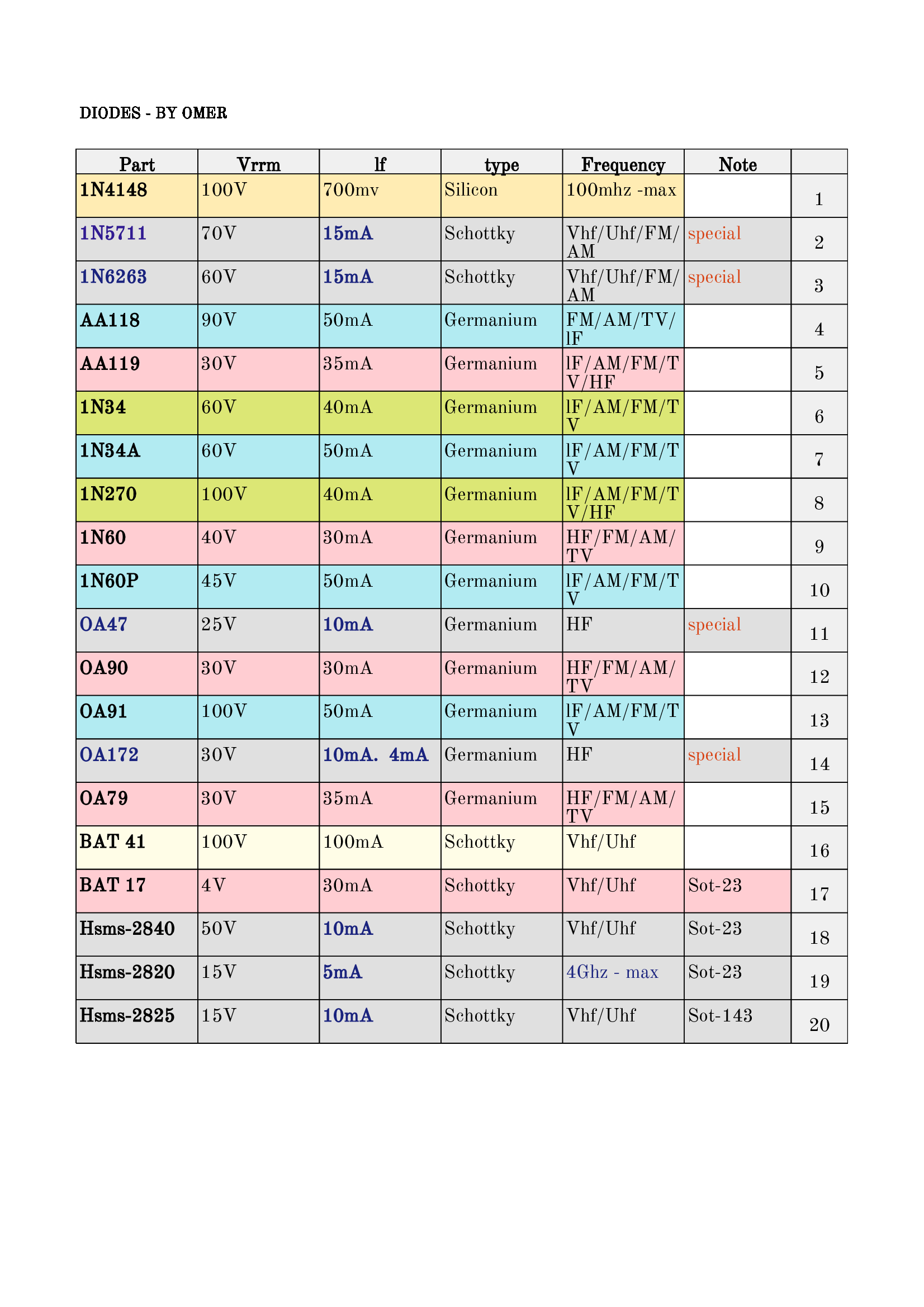
-
-
Notes on the lm567 chip
I have been experimenting on a lm567 breadboard. ...and I found the following:
$ is also affected and detects multiples of the center frequency with less sensitivity, so the detection range must be narrowed, especially with the square wave.
$ It works well with frequencies of kHz, and the higher the frequency, the greater the detection accuracy and reliability.
$ It faces problems and difficulties with very low frequencies Hz in terms of reliability and detection accuracy.
$ It needs a different approach in design to accurately detect very low frequencies.
$ The high noise of the supply voltage stops it from working.
$ Using a high variable resistor, such as 470K, to switch the center frequency is not suitable for this chip.
$ The input signal voltage is less than 20 mV and it will stop working.
$ The input signal voltage is higher than 200 mV, the bandwidth increases and the accuracy decreases
.$ The use of large capacity capacitors for the output capacitor C3 is desirable when detecting very low frequencies to increase the delay and get rid of unwanted signals
$ Connecting capacitors to connections close to the chip to reduce noise.Comment
-
Support and follow up on the idea
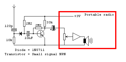
($) - Sensor section..... Wide-spectrum sensor starting from 150 khz up to approximately 3 Ghz . The source of the idea is the link below.
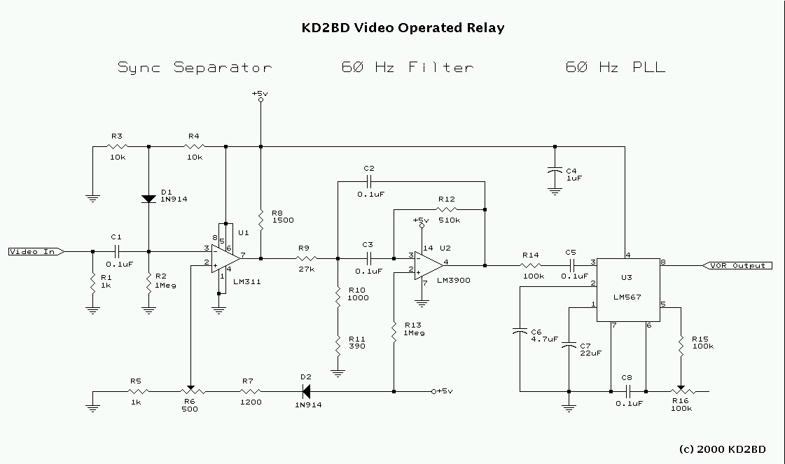
($$) - Relay section (synchronization, amplification, and signal cleaning)... to detect very low frequencies. Designed by Engineer John, link to the source page.
Comment
-
Hello...
I have been conducting experiments on a signal processor, and here I thank engineer John for this wonderful circuit that he made available to the public for general use. The initial results were very important as follows....
$ - First paragraph It has now become possible to detect very low frequencies with high accuracy and reliability. The triangle wave was tried. Things were excellent and there were no problems with detection....
$ - The second paragraph.... The problems started with the sine and square waves. We found that knowing the main frequency is not enough to detect it...
There is something called the pulse width, spacing, or pulse time, which is A type of primary frequency coding...
(For example)
to detect a 37 Hz sine wave that cannot be detected by relying only on this fundamental frequency, the pulse width must be known to calculate the coding frequency to detect that signal. In normal mode (the main frequency divided by two is the encoding frequency) to detect the main frequency (37/2 = 18.5 Hz)...
As an example, this means when dealing with a sine or square signal, the detector must be set to the encoding frequency, which is 18.5 Hz, to detect the fundamental frequency. 37 Hz outdoors....
In nature, the matter is similar. If the electrical signal is sinusoidal, the frequency and pulse width or spacing must be known to calculate the coding frequency of the signal to be detected. Note that the type of circuit filters controls the frequency pulse width. To overcome this dilemma, an appropriate detection range must be chosen. It contains the fundamental frequency and the coding frequency.Comment
-
Well done Omar! And an article describing the work. Although there is no data in the article that for normal operation of the Filter at low frequencies on the LM 567, the incoming signal must be at least 20 mV. and in some cases more. Then the microcircuit works correctly in the low frequency range.Comment
-
-
Good morning Omar! From the post you wrote, you propose an Active Search System with its own target irradiation transmitter. And if I misunderstood the translation, do you have a positive result in air or is this just a theory?Originally posted by omar View PostComment
-
Hello Bahoum... Yes, something that looks like a radar. But it's still a theoryComment
-
Good afternoon Omar! Following your theory, you propose to take the fundamental transmission frequency and look for a response at the second harmonic. At a low frequency in Hz with lm567 this is a very unstable filter. Maybe then take the Tx frequency at a higher frequency, for example 250 kHz, and receive the receiver at 125 kHz at these frequencies LM567 behaves more stably, although it will also not clearly pass 125 kHz but 125 kHz and 200 Hz above and below 124 kHz and 800 Hz. By the way, how do you expect to extract a useful signal from the desired target? The reflection of Tx will be from all that metal.Originally posted by omar View PostComment
-
Hello Bahoum....
It seems that it is very difficult for amateurs and even advanced people. Dealing with radio frequencies and radio resonance circuits, adjusting, stabilizing and powering them, is not easy. The capacitive change, if any, will be slight, and sorting it out from all this noise seems impossible. I don't know, there may be a simpler solution.
What do you think? Give us an idea or theory .Comment
-
I don't know! There seems to be a theory that the useful signal of the phenomenon is in the noise. By amplifying the signal, the noise is also amplified. It is necessary to somehow isolate the necessary signal without losses. In the Mineiro and PD Alonso circuits there is a passive filter, perhaps this is a ready-made solution.Originally posted by omar View PostComment
-
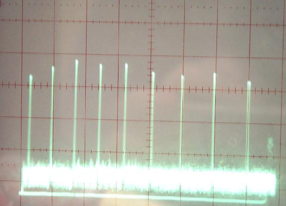
We will try to get out of the vicious circle. And find a new effective and feasible detection technique. It may be simpler than we expect. If what we are looking for is an electrical signal, it has no frequency (but it has a pulse. The number of pulses per second is the frequency of the signal in hertz). These pulses are very sharp, not like radio frequencies, they are not sine or square, but like the teeth of a comb. They may not appear on an oscilloscope. When you look at them, you think they are high frequencies in gigahertz ( modified ). This is a similarity.
And God knows best about His creation.
There is a point to be made that may seem reckless...the signal directly on the ground is 20 times stronger or more than it is in the open air.
An illustrative image of the signal shape.
Comment


Comment