
 Tweet
Tweet
Hi all
Recently I found this article below. I think this principle is what Mineoro is using in the DCH series detectors, they must have found this a long time ago. They dont use the TX for stimulation but for making the receiver very very sensitive to the signals they want.
Regards
HOW DO ATOMS DO IT?
I stumbled across the answer to my questions in a paper about VLF/ELF loop antennas. Apparently Quantum Mechanics does not supply the answer. Instead the question of small antenna behavior is resolved by a little-known section of classical electromagnetism. It involves resonance, but more importantly, it involves the magnetic and electric fields which surround any antenna. (I guess I should have expected this. After all, much of physics works fine with classical concepts, with photons and EM waves both explaining the same phenomena.)
An "electrically small" antenna is one where the physical antenna size is far smaller than the EM wavelength being received. At first glance, electrically small antennas aren't all that strange. If we use them to transmit radio waves, they work just as you'd expect. In order to force a tiny antenna to send out a large amount of EM energy, we can simply give it a huge driving signal (high voltage on a tiny dipole, or high current on a tiny loop antenna.) If the EM fields are strong at a distance of 1-wavelength from the small antenna, then the total EM radiation sent out by the antenna will be significant. It's almost as if the EM fields themselves are acting as the antenna. Weak fields act "small," while intense fields behave as a "large" antenna. This explains how a tiny antenna can transmit lots of EM. But what about reception?
It turns out that a similar idea works for reception; for "input" as opposed to "output." By manipulating the EM fields, we can force an electrically-small receiving antenna to behave as if it was very, VERY large. The secret is to intentionally impress an artificial AC field upon the receiving antenna. We'll transmit in order to receive, as it were. Conventional half-wave antennas already do exactly this because their electrons can slosh back and forth, generating their own EM fields. For example, the thin wires of a half-wave antenna are far too thin to block any incoming radio waves and absorb them. However, the current in such an antenna, as well as the voltage between the two wires, these send out large, wide, volume-filling EM fields which have a constant phase relative to the incoming waves. Because of the constant phase, these fields interact very strongly with those incoming waves. They create the lobes of an interference pattern, and this pattern has an odd characteristic: some of the incoming energy has apparently vanished. The fields produced by the antenna have cancelled out some of the energy of the impinging EM waves.
TRANSMIT IN ORDER TO RECEIVE?!!!
Rather than relying upon the wiggling electrons in the wires of the large half-wave antenna to generate EM fields... what if we used use a power supply instead? If an antenna is 1/10,000 wavelength across, we should be able to force it to behave as if it's huge; perhaps 1/3 wavelength across. We simply have to drive it hard with an RF source. We must drive it at the *same* frequency as the incoming waves, then adjust the phase and amplitude of the power supply to a special value. At one particular value, our transmissions will cause the antenna to be best at absorbing the incoming waves.
Take a loop antenna as an example. If we want our little loop-antenna to receive far more radio energy than it normally would, then we need to produce a large AC current in the antenna coil, where the phase of this current is locked in synch with the waves we wish to receive, and is lagging by 90 degrees. The voltage across the antenna terminals stays about the same as when an undriven antenna receives those waves. However, since the current is much higher in the driven antenna, the energy received per second is much higher as well. This seems like engineering blasphemy, no? How can adding a larger current increase the RECEIVED power? And won't our receiving antenna start transmitting? Yet this actually does work. Power equals volts times amps. To increase the RF power received from distant sources, we increase the antenna's amperes intentionally.
This sounds really silly. How can we improve the reception of an electrically small antenna by using it to *transmit*? The secret involves the cancellation of magnetic or electric fields in the near-field region of the antenna. The physics of the nearfield region of antennas has a kind of nonlinearity because conductors are present. In the electromagnetic nearfield region, it's possible to change the "E" of a wave without changing the "M" (change the antenna's voltage without changing the current), and vice versa. Superposition of EM traveling waves does not quite apply here because the ruling equations for energy propagation near conductors depends upon V^2 or I^2 separately. In addition, V is almost independent of I in the near-field region. If a very small loop antenna (a coil) should happen to receive a radio wave as a very small signal, we can increase the received *energy* by artificially increasing the current. Or if we're using a tiny dipole antenna (a capacitor,) we can increase the short dipole's received energy by applying a large AC voltage across the antenna terminals.
NOT CRACKPOTTY AFTER ALL
Note that this does not violate any rules of conventional physics. If we add stronger EM fields, they sum with the incoming EM plane waves and cause these radio waves to bend towards the tiny antenna, and the antenna absorbs them. This increases the antenna's EA (effective area, or effective aperture.) We can use this process to alter the coupling between the antenna and the surrounding space, but the total energy still follows the conservation law. The altered fields only change the "virtual size" or EA of the antenna.
More importantly, the phenomenon is quite limited. We can only use it with electrically "small" antennas. We cannot increase the "virtual size" much beyond a quarter wavelength for the waves involved. If we already have a large 1/2-wave dipole, then no matter how large is our artificially-add AC voltage, we cannot make it absorb more incoming waves. However, if we have an extremely small antenna, say, a 10KHz loop antenna the size of a pie plate, we can make that antenna seem very, very large indeed. Think like this: how large is the diameter of the antenna's nearfield region at 10KHz? Around 10 kilometers? What if we could extract half of the incoming energy from that entire volume?!! In theory we can: half can be absorbed, and the other half scattered. In theory a tiny loop antenna sitting on your lab bench can intercept just as much energy as a longwire 1/2-wave antenna which is 10KM long. Bizarre, eh?
Here's a way to look at the process. If I can create a field which CANCELS OUT some of the energy in an extended region surrounding a tiny antenna, this violates the law of Conservation of Energy. Field energy cannot just vanish! That's correct: if we cancel out the energy in the nearfield of an antenna, this is actually an absorption process, and the energy winds up inside the antenna circuitry. By emitting an EM field, a receiving antenna sucks EM energy into itself. If we ACTIVELY DRIVE an antenna with an "anti-wave", we will force the antenna to produce stronger fields which cancel the incoming waves, and simultaneously the antenna absorbs more energy from the EM fields in the surrounding region of space than it ordinarily would. It also emits some waves of its own. But in antenna theory these waves are identical to the received signals, and they are considered to be reflected or "scattered" from the antenna. It's a general law that we cannot receive EM waves without scattering half of the energy away again.
Here's the interesting part. If we wish to receive power rather than signals, a critical issue arises.
Driving a tiny antenna with a large signal will create large currents and heat the antenna. Small antennas are inefficient when compared to half-wave dipoles. If we wish to maximize the virtual aperature of a really tiny antenna (e.g. make our 10KHz pie-plate coil act 10KM across,) we'll quickly be frustrated by wire heating. All the extra received energy will go into warming the copper. Possible solutions: use superconductor loops, or at low frequencies use the nearest equivalent to an AC-driven superconductor: a rotating permanent magnet or rotating capacitor plates.
BUT HOW DO ATOMS DO IT?
OK, if this supposedly explains how tiny atoms can receive long light waves, how can we increase the voltage signal to a SINGLE ATOM?! Actually it's not difficult. No angstrom-sized radio transmitter is needed. The key is to use EM energy stored as oscillating fields; i.e. resonance.
If an atom resonates electromagnetically at the same frequency as the incident light waves, then, from a Classical standpoint, that atom's internal resonator will store EM energy accumulated from the incoming waves. It will then behave as an oscillator, becoming surrounded by an increasingly strong AC electromagnetic field as time goes by. (Quantum Mechanics might say that the atom is surrounded by virtual photons at the resonant frequency.) If this alternating field is locked into the correct phase with the incoming light wave, then the atom's fields can interact with the light waves' fields and cancel out quite a bit of the light energy present in the nearfield region around the atom. The energy doesn't vanish, instead it ends up INSIDE the atom. Half of the energy goes into kicking an electron to a higher level, and the other half is re-emitted as "scattered" waves.
By resonantly creating an "anti-wave", which superposes with incoming waves and bends them towards the atom, the tiny atom has "sucked energy" out of the enormously long light waves as they go by. And since the atom has no conventional copper coils inside it wasting energy, it can build up some really strong fields which allow it to behave extremely "large" when compared to it's physical diameter.
Impossible? Please track down the C. Bohren paper in the references below. He analyzes the behavior of small metal particles and dielectric particles exposed to long-wave EM radiation, and rigorously shows with semi-Classical analysis that the presance of a resonator can cause dust motes to "act larger than they really are."
How can this stuff be true?! After all, electric and magnetic fields cannot BEND other fields. They cannot affect each other directly. They work by superposition. For the same reason, a light wave cannot deflect another light wave. Ah, but as I said before, the mathematics of the fields around a coil or a capacitor are not the same as the mathematics of freely-propagating EM waves. If we add the field of a bar magnet to the field of a radio wave, and if the bar magnet is in the right place (at a spot where the phase of the b-field of the radio wave is reversing polarity,) then the radio wave becomes distorted in such a way that it momentarily bends towards the bar magnet. And then, as the EM wave progresses, we must flip the magnet over and over in order to keep the field pattern from bending away again during the following half-cycle. The energy flow continues to "funnel in" towards the rotating magnet. Now replace the bar magnet with an AC coil, and vary the coil current so the fields stay locked to the traveling radio wave in the same way. In that case the wave energy will ALWAYS bend towards the coil and be absorbed. Superposition still applies, but this is a COHERENT superposition, so it acts like a static field pattern: as if a permanent magnet can bend a radio wave inwards and absorb its energy rather than simply having the fields sum together without interesting results.
Note that the coil will also emit its own EM ripple. This emission is well known: atoms ideally will scatter half the light they absorb, and dipole antennas behave similarly: they scatterer incoming EM waves as they absorb part of the energy. When all is said and done, our oscillating coil has absorbed half of the incoming EM energy and re-emitted (or "scattered") the rest. In a phase-locked system, we cannot tell the difference between reflection and transmission.
A "HOLE" IN PHYSICS
When viewed as a halfwave receiving antenna, a resonant atom acts as if it has expanded in size to fill its entire nearfield region. In terms of Quantum Mechanics, it does so by locally creating a large virtual-photon AC field which normally would not exist. Because of coherent superposition, in a sense this new field BECOMES THE ANTENNA. The significant part of this new field extends to (Pi*wavelength)/2 distance around the atom, and this distance can be thousands of times larger than the atom's radius. A 1-angstrom atom with a large AC field can behave as a 1/3-wave antenna at optical frequencies. Though tiny, the atom can absorb "longwave" radiation such as light. Our 1-angstrom atom becomes a black sphere 2000 angstroms across, and efficiently absorbs 6000-Angstrom light waves. Very strange, no? I've certainly never encountered such a thing during my physics training. Apparently the missing details of the absorption of light wave by atoms is a "hole" in physics education, and it has only been treated in a couple of contemporary physics papers in the 1980s. Here's another hole: when an atom absorbs waves, it has to scatter away half the energy. Does this mean that when an atom absorbs a photon, it must always interact with TWO photons, eating one and reflecting the other?!!!! I've never heard of such a requirement. It flys in the face of the usual description of atoms and photons. (Is it mentioned in Feynman's QED book?)
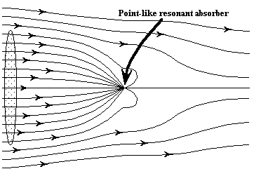
Fig 1. Energy flux lines for the nearfield region of
a resonant absorber. The tiny absorber acts like
a large disk.
[from ref#4]
This "energy suction" effect is not limited to atoms. We can easily build a device to demonstrate the phenomenon. Below is a simple physics analogy to show how tiny atoms can "suck energy" from long light waves. Suppose we transmit a VLF radio signal at 1KHZ frequency. Let's arbitrarily set the signal strength so it's about the same strength as the Earth's weak vertical e-field: 100 Volt/meter. If the transmitter's e-field is contained entirely below the conductive ionosphere, and if the bottom of the ionosphere is about 100Km high, then the Earth's entire vertical field is about 10 megavolts top to bottom. Our transmitter must produce such a field. These values aren't totally ridiculous. Large, well-designed Tesla coils commonly produce 10 megavolts. If such a coil was erected outdoors and connected to an insulated metal tower, it would fill the Earth's entire atmosphere with 1KHz radiation. The Earth's atmosphere would be like a microwave oven cavity. Such an AC voltage field would produce a feeble 100V/M field everywhere on the Earth's surface. This field would be detectable by instruments, but otherwise it would be too small for humans to notice, and we certainly would not expect to be able to get significant power out of it.
CAPACITIVE-PLATE ANTENNA
OK, we've got a feeble AC e-field in the outdoor environment. How will a simple antenna-plate perform as an energy receiver? See fig.2 below. If it's a large horizontal metal plate about one meter off the ground, it will give out a 100 volt signal at 1KHz, but this one hundred volt "power source" has an extremely large capacitive series impedance. Let's say that the plate/ground capacitance is 10pF. To draw energy with the maximum possible voltage, the load resistor should be approximately equal to the series impedance. This impedance is dominated by the 10pF capacitor value, so this gives 1/(2*PI*F*C) = 16 megohm load resistor, and it drags the antenna's voltage down from 100V to 70.7V. The received energy in the resistor is 300 microwatts, and the current in the resistor is in the microamp range. Just as we might expect, everything here is similar to a conventional radio antenna. The weak e-field from the incoming EM waves behaves only as a "signal", and it is not a source of significant power. It can't drive a motor or light an LED.
__________ --> | 10 MVolt |_______ | @ 1KHz | | |__________| | | ___|___ Capacitance from ionosphere to plate _|_ ( very small, say 1/10,000 pF ) //// _______ | | |______________ <--- 70.7V @ 1KHz antenna | | (metal plate) ___|___ \ 10pF / 16.7 Megohm _______ \ | / |______________| _|_ //// FIGURE 2
The fundamental problem with the above system is that the empty space around our metal plate is acting like a voltage divider. If the sky has 10 Megavolts compared to ground, and if the metal plate is a few feet above the surface of the ground, then the plate only has a relatively tiny voltage. Current is tiny, so wattage is also tiny. Maybe we could power an LED flasher with this antenna... but only if we set it to flash every few minutes. Maybe if we erected an enormous antenna tower we could do better by lifting the plate higher from the ground (but with such a huge antenna, we could easily steal more power by ignoring our 1KHz broadcast, because many high-power conventional AM radio stations exist: BBC shortwave, Voice of America, etc.)
RESONANT ANTENNA
Now lets add a tuned circuit to the above schematic and see what happens:
__________ --> | 10 MVolt |_______ | @ 1KHz | | |__________| | | ___|___ Capacitance from ionosphere to plate _|_ ( very small, say 1/10,000 pF ) //// _______ | | |_____________ <--- 10 Megavolts! | | antenna | \_ (metal plate) ___|___ (_) 10pF (_) Coil _______ (_) | (_) | / |____________| | _|_ 1KHz resonant, infinite Q //// FIGURE 3At resonance, the 10pF capacitance of our metal plate effectively vanishes. At resonance, an ideal parallel-resonant circuit behaves like an infinite resistor. If the LC circuit is exactly at resonance, and neglecting the resistance of the wires involved, how high will the voltage on the metal plate rise? It rises to ten megavolts!!!! The resonant circuit will continuously accumulate EM energy until the voltage at the antenna-plate rises to the same value of voltage as the transmitter. Weird!
Keep in mind that this device is a relatively small affair sitting in your back yard. It's not a 1KHz quarter-wave dipole tower 25 miles tall. There's no huge antenna, so we would not expect to find any huge level of electric power appearing in the circuit. If we weren't aware of the mechanism behind this, all we'd see is a passive LC resonator which seems to burst into oscillation of its own accord, and the voltage grows higher and higher until the darned thing suffers a corona outbreak or something. Lightning bolts shoot out! The EM fields near the metal plate grow FAR STRONGER than the weak fields already present in the environment. The device in our back yard resembles an impossible "perpetual motion" machine, which might make physicists suspect a hoax. However, the real explanation is completely conventional, and the source of the energy is a feeble, unnoticed AC e-field field produced by the very distant 10-megavolt transmitter tower. Note: the above phenomenon can only occur for an ideal LC circuit, where the resistance of the coil is zero and where the Q of the circuit is infinite. If our antenna plate were connected to the resonant "secondary" of a superconductive Tesla coil, we might in fact see the output voltage grow to the megavolt range. However, in most real-world tuned circuits it wouldn't reach such heights.
But remember, voltage is not energy. What will be the realistic behavior of such a device? Perhaps the incoming power is still small (maybe like 300 microwatts we saw earlier), or perhaps it works well, yet it takes months to build up so much voltage across even a superconductor resonator Just what is the actual received energy flow? Let's put a resistor across the tuned circuit so we create a flow of real energy and drag the voltage down to, say, .707 of the unloaded voltage. The resistance should equal the impedance of the series capacitor: 10 ^ -16 Farads, giving 1600 giga-ohms. (A huge resistor. Clearly it makes sense to try instead to extract energy using a low-value resistor in series with the inductor coil, rather than using a huge parallel resistor across the tuned circuit. A 1.6 tera-ohm power-resistor might be hard to find in the surplus parts catalogs! That is, if you don't have the parts- catalog featured in THIS ISLAND EARTH, that old SF movie where the two engineers build an "Interociter" from parts sold by mail-order in a strange electronics catalog. Obviously the Interociter is Alien Tesla coil technology, aha!)
Ahem.
HUGE RECEIVED POWER
With our 1.6 giga-megohm resistor in place, the RF power intercepted by the small metal plate is now 30 watts. That's ONE HUNDRED THOUSAND TIMES HIGHER than the power from the simple non-resonant antenna plate. Our tiny antenna has essentially reached out and made a kind of "direct contact" with the distant transmitter. By changing its own impedance, it has converted the femtofarad "sky capacitor" into an efficient coupling device. It has sent out a cancelling wave and pulled in energy from an enormous volume encompassing the surrounding fields. It has become a "matching transformer" which steps down the 10MV sky voltage and steps up the "sky current." If we either increase the receiver plate's size, or lift it up high on an antenna tower, or connect it to a beam of x-rays which produce an ionized pathway extending vertically upwards, then the received power rises proportionally.
So, connect a high-Q resonator to a small antenna, and you'll drag in far more wave energy. Simple?
[The engineers on SCI.ELECTRONICS.DESIGN forum have pointed out that the 10MV voltage limit on the above resonator is wrong. In reality, it can grow much higher than the voltage on the transmitter. The system is actually series-resonant, so the output voltage is limited only by the Q of the system (by the resistance of the wires in the resonator coil) and is not limited by the 10MV drive voltage of the distant transmitter.]
In our earlier antenna, (the nonresonant, resistor-only version,) a small amount of "real power" did take a path through the capacitance of the sky while on its way to the metal plate and to the load resistor. If the voltage across that resistor could be forced to oscillate hugely, and if it had the right phase compared to the tiny displacement current coming from the transmitter, then we'd obtain a major increase in energy flow. The tiny sky-current would remain about the same, but with the much larger voltage on the antenna, the value for V*I is increased and wattage is increased. Remember the unwanted capacitive-voltage-divider effect in figure 2? With a resonant system, that effect would no longer apply, and the output voltage would no longer be so low. Things would behave differently. The displacement-current going through the "sky capacitor" might still be microamps, but if the tuned circuit can alter the high voltage at our end of the transmission system, then it can drastically change the energy throughput. As with any power-transmission system, we can put more power through it by raising the line voltage while keeping the current the same.
CONCLUSION
To sum up: we see that by putting a big AC voltage on the tuned circuit and by adjusting its phase in relation to the tiny incoming current, we can "suck" the E x M wattage from the enormously broad wavefronts of the incoming waves. It also works this way inside a simple circuit using conventional voltage dividers: add a resonant circuit, and the series impedance of the power source behaves smaller. See this example circuit. It should still work this way even when a part of the antenna circuit contains a series capacitor whose dielectric is made up of many feet (or even tens of km) of empty space. It's very much like building a high-voltage power line: to transmit high wattage on a thin wire, we use high voltage at low current, and then we put a step-down transformer at the far end of the power line. However, in the "power line" shown in the above diagram, we then put a tiny capacitor in series with the high-voltage line. Then we increase the thickness of the capacitor's air-dielectric until dielectric is miles thick and the current in the system is mostly composed of displacement current in the empty space between the pair of widely-separated capacitor plates. To transmit significant power, step the voltage up to astronomical levels at one end, then step it back down at the other end. Rather than using only a step-down transformer in the receiver, instead we use a hi-Q resonator, and we allow the resonant voltage to rise to a huge value. As a result, EM energy will be "sucked" into the receiver.
Recently I found this article below. I think this principle is what Mineoro is using in the DCH series detectors, they must have found this a long time ago. They dont use the TX for stimulation but for making the receiver very very sensitive to the signals they want.
Regards
HOW DO ATOMS DO IT?
I stumbled across the answer to my questions in a paper about VLF/ELF loop antennas. Apparently Quantum Mechanics does not supply the answer. Instead the question of small antenna behavior is resolved by a little-known section of classical electromagnetism. It involves resonance, but more importantly, it involves the magnetic and electric fields which surround any antenna. (I guess I should have expected this. After all, much of physics works fine with classical concepts, with photons and EM waves both explaining the same phenomena.)
An "electrically small" antenna is one where the physical antenna size is far smaller than the EM wavelength being received. At first glance, electrically small antennas aren't all that strange. If we use them to transmit radio waves, they work just as you'd expect. In order to force a tiny antenna to send out a large amount of EM energy, we can simply give it a huge driving signal (high voltage on a tiny dipole, or high current on a tiny loop antenna.) If the EM fields are strong at a distance of 1-wavelength from the small antenna, then the total EM radiation sent out by the antenna will be significant. It's almost as if the EM fields themselves are acting as the antenna. Weak fields act "small," while intense fields behave as a "large" antenna. This explains how a tiny antenna can transmit lots of EM. But what about reception?
It turns out that a similar idea works for reception; for "input" as opposed to "output." By manipulating the EM fields, we can force an electrically-small receiving antenna to behave as if it was very, VERY large. The secret is to intentionally impress an artificial AC field upon the receiving antenna. We'll transmit in order to receive, as it were. Conventional half-wave antennas already do exactly this because their electrons can slosh back and forth, generating their own EM fields. For example, the thin wires of a half-wave antenna are far too thin to block any incoming radio waves and absorb them. However, the current in such an antenna, as well as the voltage between the two wires, these send out large, wide, volume-filling EM fields which have a constant phase relative to the incoming waves. Because of the constant phase, these fields interact very strongly with those incoming waves. They create the lobes of an interference pattern, and this pattern has an odd characteristic: some of the incoming energy has apparently vanished. The fields produced by the antenna have cancelled out some of the energy of the impinging EM waves.
TRANSMIT IN ORDER TO RECEIVE?!!!
Rather than relying upon the wiggling electrons in the wires of the large half-wave antenna to generate EM fields... what if we used use a power supply instead? If an antenna is 1/10,000 wavelength across, we should be able to force it to behave as if it's huge; perhaps 1/3 wavelength across. We simply have to drive it hard with an RF source. We must drive it at the *same* frequency as the incoming waves, then adjust the phase and amplitude of the power supply to a special value. At one particular value, our transmissions will cause the antenna to be best at absorbing the incoming waves.
Take a loop antenna as an example. If we want our little loop-antenna to receive far more radio energy than it normally would, then we need to produce a large AC current in the antenna coil, where the phase of this current is locked in synch with the waves we wish to receive, and is lagging by 90 degrees. The voltage across the antenna terminals stays about the same as when an undriven antenna receives those waves. However, since the current is much higher in the driven antenna, the energy received per second is much higher as well. This seems like engineering blasphemy, no? How can adding a larger current increase the RECEIVED power? And won't our receiving antenna start transmitting? Yet this actually does work. Power equals volts times amps. To increase the RF power received from distant sources, we increase the antenna's amperes intentionally.
This sounds really silly. How can we improve the reception of an electrically small antenna by using it to *transmit*? The secret involves the cancellation of magnetic or electric fields in the near-field region of the antenna. The physics of the nearfield region of antennas has a kind of nonlinearity because conductors are present. In the electromagnetic nearfield region, it's possible to change the "E" of a wave without changing the "M" (change the antenna's voltage without changing the current), and vice versa. Superposition of EM traveling waves does not quite apply here because the ruling equations for energy propagation near conductors depends upon V^2 or I^2 separately. In addition, V is almost independent of I in the near-field region. If a very small loop antenna (a coil) should happen to receive a radio wave as a very small signal, we can increase the received *energy* by artificially increasing the current. Or if we're using a tiny dipole antenna (a capacitor,) we can increase the short dipole's received energy by applying a large AC voltage across the antenna terminals.
NOT CRACKPOTTY AFTER ALL
Note that this does not violate any rules of conventional physics. If we add stronger EM fields, they sum with the incoming EM plane waves and cause these radio waves to bend towards the tiny antenna, and the antenna absorbs them. This increases the antenna's EA (effective area, or effective aperture.) We can use this process to alter the coupling between the antenna and the surrounding space, but the total energy still follows the conservation law. The altered fields only change the "virtual size" or EA of the antenna.
More importantly, the phenomenon is quite limited. We can only use it with electrically "small" antennas. We cannot increase the "virtual size" much beyond a quarter wavelength for the waves involved. If we already have a large 1/2-wave dipole, then no matter how large is our artificially-add AC voltage, we cannot make it absorb more incoming waves. However, if we have an extremely small antenna, say, a 10KHz loop antenna the size of a pie plate, we can make that antenna seem very, very large indeed. Think like this: how large is the diameter of the antenna's nearfield region at 10KHz? Around 10 kilometers? What if we could extract half of the incoming energy from that entire volume?!! In theory we can: half can be absorbed, and the other half scattered. In theory a tiny loop antenna sitting on your lab bench can intercept just as much energy as a longwire 1/2-wave antenna which is 10KM long. Bizarre, eh?
Here's a way to look at the process. If I can create a field which CANCELS OUT some of the energy in an extended region surrounding a tiny antenna, this violates the law of Conservation of Energy. Field energy cannot just vanish! That's correct: if we cancel out the energy in the nearfield of an antenna, this is actually an absorption process, and the energy winds up inside the antenna circuitry. By emitting an EM field, a receiving antenna sucks EM energy into itself. If we ACTIVELY DRIVE an antenna with an "anti-wave", we will force the antenna to produce stronger fields which cancel the incoming waves, and simultaneously the antenna absorbs more energy from the EM fields in the surrounding region of space than it ordinarily would. It also emits some waves of its own. But in antenna theory these waves are identical to the received signals, and they are considered to be reflected or "scattered" from the antenna. It's a general law that we cannot receive EM waves without scattering half of the energy away again.
Here's the interesting part. If we wish to receive power rather than signals, a critical issue arises.
Driving a tiny antenna with a large signal will create large currents and heat the antenna. Small antennas are inefficient when compared to half-wave dipoles. If we wish to maximize the virtual aperature of a really tiny antenna (e.g. make our 10KHz pie-plate coil act 10KM across,) we'll quickly be frustrated by wire heating. All the extra received energy will go into warming the copper. Possible solutions: use superconductor loops, or at low frequencies use the nearest equivalent to an AC-driven superconductor: a rotating permanent magnet or rotating capacitor plates.
BUT HOW DO ATOMS DO IT?
OK, if this supposedly explains how tiny atoms can receive long light waves, how can we increase the voltage signal to a SINGLE ATOM?! Actually it's not difficult. No angstrom-sized radio transmitter is needed. The key is to use EM energy stored as oscillating fields; i.e. resonance.
If an atom resonates electromagnetically at the same frequency as the incident light waves, then, from a Classical standpoint, that atom's internal resonator will store EM energy accumulated from the incoming waves. It will then behave as an oscillator, becoming surrounded by an increasingly strong AC electromagnetic field as time goes by. (Quantum Mechanics might say that the atom is surrounded by virtual photons at the resonant frequency.) If this alternating field is locked into the correct phase with the incoming light wave, then the atom's fields can interact with the light waves' fields and cancel out quite a bit of the light energy present in the nearfield region around the atom. The energy doesn't vanish, instead it ends up INSIDE the atom. Half of the energy goes into kicking an electron to a higher level, and the other half is re-emitted as "scattered" waves.
By resonantly creating an "anti-wave", which superposes with incoming waves and bends them towards the atom, the tiny atom has "sucked energy" out of the enormously long light waves as they go by. And since the atom has no conventional copper coils inside it wasting energy, it can build up some really strong fields which allow it to behave extremely "large" when compared to it's physical diameter.
Impossible? Please track down the C. Bohren paper in the references below. He analyzes the behavior of small metal particles and dielectric particles exposed to long-wave EM radiation, and rigorously shows with semi-Classical analysis that the presance of a resonator can cause dust motes to "act larger than they really are."
How can this stuff be true?! After all, electric and magnetic fields cannot BEND other fields. They cannot affect each other directly. They work by superposition. For the same reason, a light wave cannot deflect another light wave. Ah, but as I said before, the mathematics of the fields around a coil or a capacitor are not the same as the mathematics of freely-propagating EM waves. If we add the field of a bar magnet to the field of a radio wave, and if the bar magnet is in the right place (at a spot where the phase of the b-field of the radio wave is reversing polarity,) then the radio wave becomes distorted in such a way that it momentarily bends towards the bar magnet. And then, as the EM wave progresses, we must flip the magnet over and over in order to keep the field pattern from bending away again during the following half-cycle. The energy flow continues to "funnel in" towards the rotating magnet. Now replace the bar magnet with an AC coil, and vary the coil current so the fields stay locked to the traveling radio wave in the same way. In that case the wave energy will ALWAYS bend towards the coil and be absorbed. Superposition still applies, but this is a COHERENT superposition, so it acts like a static field pattern: as if a permanent magnet can bend a radio wave inwards and absorb its energy rather than simply having the fields sum together without interesting results.
Note that the coil will also emit its own EM ripple. This emission is well known: atoms ideally will scatter half the light they absorb, and dipole antennas behave similarly: they scatterer incoming EM waves as they absorb part of the energy. When all is said and done, our oscillating coil has absorbed half of the incoming EM energy and re-emitted (or "scattered") the rest. In a phase-locked system, we cannot tell the difference between reflection and transmission.
A "HOLE" IN PHYSICS
When viewed as a halfwave receiving antenna, a resonant atom acts as if it has expanded in size to fill its entire nearfield region. In terms of Quantum Mechanics, it does so by locally creating a large virtual-photon AC field which normally would not exist. Because of coherent superposition, in a sense this new field BECOMES THE ANTENNA. The significant part of this new field extends to (Pi*wavelength)/2 distance around the atom, and this distance can be thousands of times larger than the atom's radius. A 1-angstrom atom with a large AC field can behave as a 1/3-wave antenna at optical frequencies. Though tiny, the atom can absorb "longwave" radiation such as light. Our 1-angstrom atom becomes a black sphere 2000 angstroms across, and efficiently absorbs 6000-Angstrom light waves. Very strange, no? I've certainly never encountered such a thing during my physics training. Apparently the missing details of the absorption of light wave by atoms is a "hole" in physics education, and it has only been treated in a couple of contemporary physics papers in the 1980s. Here's another hole: when an atom absorbs waves, it has to scatter away half the energy. Does this mean that when an atom absorbs a photon, it must always interact with TWO photons, eating one and reflecting the other?!!!! I've never heard of such a requirement. It flys in the face of the usual description of atoms and photons. (Is it mentioned in Feynman's QED book?)
Fig 1. Energy flux lines for the nearfield region of
a resonant absorber. The tiny absorber acts like
a large disk.
[from ref#4]
This "energy suction" effect is not limited to atoms. We can easily build a device to demonstrate the phenomenon. Below is a simple physics analogy to show how tiny atoms can "suck energy" from long light waves. Suppose we transmit a VLF radio signal at 1KHZ frequency. Let's arbitrarily set the signal strength so it's about the same strength as the Earth's weak vertical e-field: 100 Volt/meter. If the transmitter's e-field is contained entirely below the conductive ionosphere, and if the bottom of the ionosphere is about 100Km high, then the Earth's entire vertical field is about 10 megavolts top to bottom. Our transmitter must produce such a field. These values aren't totally ridiculous. Large, well-designed Tesla coils commonly produce 10 megavolts. If such a coil was erected outdoors and connected to an insulated metal tower, it would fill the Earth's entire atmosphere with 1KHz radiation. The Earth's atmosphere would be like a microwave oven cavity. Such an AC voltage field would produce a feeble 100V/M field everywhere on the Earth's surface. This field would be detectable by instruments, but otherwise it would be too small for humans to notice, and we certainly would not expect to be able to get significant power out of it.
CAPACITIVE-PLATE ANTENNA
OK, we've got a feeble AC e-field in the outdoor environment. How will a simple antenna-plate perform as an energy receiver? See fig.2 below. If it's a large horizontal metal plate about one meter off the ground, it will give out a 100 volt signal at 1KHz, but this one hundred volt "power source" has an extremely large capacitive series impedance. Let's say that the plate/ground capacitance is 10pF. To draw energy with the maximum possible voltage, the load resistor should be approximately equal to the series impedance. This impedance is dominated by the 10pF capacitor value, so this gives 1/(2*PI*F*C) = 16 megohm load resistor, and it drags the antenna's voltage down from 100V to 70.7V. The received energy in the resistor is 300 microwatts, and the current in the resistor is in the microamp range. Just as we might expect, everything here is similar to a conventional radio antenna. The weak e-field from the incoming EM waves behaves only as a "signal", and it is not a source of significant power. It can't drive a motor or light an LED.
__________ --> | 10 MVolt |_______ | @ 1KHz | | |__________| | | ___|___ Capacitance from ionosphere to plate _|_ ( very small, say 1/10,000 pF ) //// _______ | | |______________ <--- 70.7V @ 1KHz antenna | | (metal plate) ___|___ \ 10pF / 16.7 Megohm _______ \ | / |______________| _|_ //// FIGURE 2
The fundamental problem with the above system is that the empty space around our metal plate is acting like a voltage divider. If the sky has 10 Megavolts compared to ground, and if the metal plate is a few feet above the surface of the ground, then the plate only has a relatively tiny voltage. Current is tiny, so wattage is also tiny. Maybe we could power an LED flasher with this antenna... but only if we set it to flash every few minutes. Maybe if we erected an enormous antenna tower we could do better by lifting the plate higher from the ground (but with such a huge antenna, we could easily steal more power by ignoring our 1KHz broadcast, because many high-power conventional AM radio stations exist: BBC shortwave, Voice of America, etc.)
RESONANT ANTENNA
Now lets add a tuned circuit to the above schematic and see what happens:
__________ --> | 10 MVolt |_______ | @ 1KHz | | |__________| | | ___|___ Capacitance from ionosphere to plate _|_ ( very small, say 1/10,000 pF ) //// _______ | | |_____________ <--- 10 Megavolts! | | antenna | \_ (metal plate) ___|___ (_) 10pF (_) Coil _______ (_) | (_) | / |____________| | _|_ 1KHz resonant, infinite Q //// FIGURE 3At resonance, the 10pF capacitance of our metal plate effectively vanishes. At resonance, an ideal parallel-resonant circuit behaves like an infinite resistor. If the LC circuit is exactly at resonance, and neglecting the resistance of the wires involved, how high will the voltage on the metal plate rise? It rises to ten megavolts!!!! The resonant circuit will continuously accumulate EM energy until the voltage at the antenna-plate rises to the same value of voltage as the transmitter. Weird!
Keep in mind that this device is a relatively small affair sitting in your back yard. It's not a 1KHz quarter-wave dipole tower 25 miles tall. There's no huge antenna, so we would not expect to find any huge level of electric power appearing in the circuit. If we weren't aware of the mechanism behind this, all we'd see is a passive LC resonator which seems to burst into oscillation of its own accord, and the voltage grows higher and higher until the darned thing suffers a corona outbreak or something. Lightning bolts shoot out! The EM fields near the metal plate grow FAR STRONGER than the weak fields already present in the environment. The device in our back yard resembles an impossible "perpetual motion" machine, which might make physicists suspect a hoax. However, the real explanation is completely conventional, and the source of the energy is a feeble, unnoticed AC e-field field produced by the very distant 10-megavolt transmitter tower. Note: the above phenomenon can only occur for an ideal LC circuit, where the resistance of the coil is zero and where the Q of the circuit is infinite. If our antenna plate were connected to the resonant "secondary" of a superconductive Tesla coil, we might in fact see the output voltage grow to the megavolt range. However, in most real-world tuned circuits it wouldn't reach such heights.
But remember, voltage is not energy. What will be the realistic behavior of such a device? Perhaps the incoming power is still small (maybe like 300 microwatts we saw earlier), or perhaps it works well, yet it takes months to build up so much voltage across even a superconductor resonator Just what is the actual received energy flow? Let's put a resistor across the tuned circuit so we create a flow of real energy and drag the voltage down to, say, .707 of the unloaded voltage. The resistance should equal the impedance of the series capacitor: 10 ^ -16 Farads, giving 1600 giga-ohms. (A huge resistor. Clearly it makes sense to try instead to extract energy using a low-value resistor in series with the inductor coil, rather than using a huge parallel resistor across the tuned circuit. A 1.6 tera-ohm power-resistor might be hard to find in the surplus parts catalogs! That is, if you don't have the parts- catalog featured in THIS ISLAND EARTH, that old SF movie where the two engineers build an "Interociter" from parts sold by mail-order in a strange electronics catalog. Obviously the Interociter is Alien Tesla coil technology, aha!)
Ahem.
HUGE RECEIVED POWER
With our 1.6 giga-megohm resistor in place, the RF power intercepted by the small metal plate is now 30 watts. That's ONE HUNDRED THOUSAND TIMES HIGHER than the power from the simple non-resonant antenna plate. Our tiny antenna has essentially reached out and made a kind of "direct contact" with the distant transmitter. By changing its own impedance, it has converted the femtofarad "sky capacitor" into an efficient coupling device. It has sent out a cancelling wave and pulled in energy from an enormous volume encompassing the surrounding fields. It has become a "matching transformer" which steps down the 10MV sky voltage and steps up the "sky current." If we either increase the receiver plate's size, or lift it up high on an antenna tower, or connect it to a beam of x-rays which produce an ionized pathway extending vertically upwards, then the received power rises proportionally.
So, connect a high-Q resonator to a small antenna, and you'll drag in far more wave energy. Simple?
[The engineers on SCI.ELECTRONICS.DESIGN forum have pointed out that the 10MV voltage limit on the above resonator is wrong. In reality, it can grow much higher than the voltage on the transmitter. The system is actually series-resonant, so the output voltage is limited only by the Q of the system (by the resistance of the wires in the resonator coil) and is not limited by the 10MV drive voltage of the distant transmitter.]
In our earlier antenna, (the nonresonant, resistor-only version,) a small amount of "real power" did take a path through the capacitance of the sky while on its way to the metal plate and to the load resistor. If the voltage across that resistor could be forced to oscillate hugely, and if it had the right phase compared to the tiny displacement current coming from the transmitter, then we'd obtain a major increase in energy flow. The tiny sky-current would remain about the same, but with the much larger voltage on the antenna, the value for V*I is increased and wattage is increased. Remember the unwanted capacitive-voltage-divider effect in figure 2? With a resonant system, that effect would no longer apply, and the output voltage would no longer be so low. Things would behave differently. The displacement-current going through the "sky capacitor" might still be microamps, but if the tuned circuit can alter the high voltage at our end of the transmission system, then it can drastically change the energy throughput. As with any power-transmission system, we can put more power through it by raising the line voltage while keeping the current the same.
CONCLUSION
To sum up: we see that by putting a big AC voltage on the tuned circuit and by adjusting its phase in relation to the tiny incoming current, we can "suck" the E x M wattage from the enormously broad wavefronts of the incoming waves. It also works this way inside a simple circuit using conventional voltage dividers: add a resonant circuit, and the series impedance of the power source behaves smaller. See this example circuit. It should still work this way even when a part of the antenna circuit contains a series capacitor whose dielectric is made up of many feet (or even tens of km) of empty space. It's very much like building a high-voltage power line: to transmit high wattage on a thin wire, we use high voltage at low current, and then we put a step-down transformer at the far end of the power line. However, in the "power line" shown in the above diagram, we then put a tiny capacitor in series with the high-voltage line. Then we increase the thickness of the capacitor's air-dielectric until dielectric is miles thick and the current in the system is mostly composed of displacement current in the empty space between the pair of widely-separated capacitor plates. To transmit significant power, step the voltage up to astronomical levels at one end, then step it back down at the other end. Rather than using only a step-down transformer in the receiver, instead we use a hi-Q resonator, and we allow the resonant voltage to rise to a huge value. As a result, EM energy will be "sucked" into the receiver.


 principle.
Comment