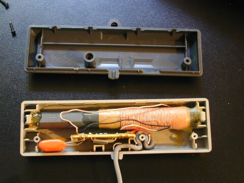
Here is my PDK housing for the Alonso Clone. I needed some good housing to do the calibration exactly. I've designed my own housing in AutoCad Light and used my DIY CNC Router to create the parts. Now I have to search for an approriate Ferriterod.
Nice.
Did you design the CNC router yourself, or is it from a kit?
Thanks! Actually it's a kit I've bought many years ago. I did also design my own CNC router but that complete kit with controller was much cheaper. Nowadays you get full CNC router incl. software for smaller price because competition is very high.
Congratulation for your fantastic design.
You must know that at original Alonso's PD, Omega coil looks at top of housing (you must turn it 180 degrees).
Hi all
Sorry for delay send about more infos for PD. After experiments, three months ago, i see PD need new circuits design. I make new design with new extra circuits for more stability , filters etc. Attachment inside PD a photo. I hope next week i have final experiments of course video etc.
About reject magnetics or soil lines, ground effects, full rejection all metals except Gold, rain, AC camples 220v, temperature etc, has been solved.
About searching without motion or very slow motion PD work has been solved.
best regards
hi all
thank you very much Professor Andreas for sharing your projects, I realized your pd but I encountered some problems
1- my setup works as a Pulse induction because it detects all metal 50 mm
2- both led blinking but no sound only if I connect the Q4 collector to the resistance R40,maybe the 555 timer is blown I do not know
please help me
thank you in advance
hi all
thank you very much Professor Andreas for sharing your projects, I realized your pd but I encountered some problems
1- my setup works as a Pulse induction because it detects all metal 50 mm
2- both led blinking but no sound only if I connect the Q4 collector to the resistance R40,maybe the 555 timer is blown I do not know
please help me
thank you in advance
Hi ouiarabe
PCB and schematic have not error. I am sure 100%, before publish here and of course first prototype work with this. I think you have put "bad part" or put "invert" 555
My opinion.
Check botom side pcb with your eyes, step by step for problems
Check soldering if are correct
and final replace 555 and Q4 with new
The best choice is .. use osciloscope and check all sections if you have a friend electronic engineer
best regards
accept my respectful greetings ANDREAS teacher and thank you I'll check and change the IC 555 and T4 and attach images and video of the printed circuit
Hi ouiarabe
PCB and schematic have not error. I am sure 100%, before publish here and of course first prototype work with this. I think you have put "bad part" or put "invert" 555
My opinion.
Check botom side pcb with your eyes, step by step for problems
Check soldering if are correct
and final replace 555 and Q4 with new
The best choice is .. use osciloscope and check all sections if you have a friend electronic engineer
best regards
hi professor ANDREAS
I checked all the welds and change the NE555 and Q4 but its same problem I will attach a video
thank you for your help and I await your recommendations with pacience
thank you in advance.
hi professor ANDREAS
I checked all the welds and change the NE555 and Q4 but its same problem I will attach a video
thank you for your help and I await your recommendations with pacience
thank you in advance.
Via a video i cannot find solution, but maybe...
Unconnect C15 and connect power supply. If you have the same tic-tic on buzzer, replace buzzer with other attchment pic.
best regards
Comment