Announcement

Collapse
No announcement yet.

Protek Gtx 711

Collapse
X
 
  • Filter
  • Time
  • Show
Clear All
new posts

  • #61
    Originally posted by Dubulumach View Post
    Русские Рамки
    Hello Dubulumach!
    Nice, but what are the measurements of the pot core ferrite? without correct, precise, functional receiver heads of the pot core ferrite nothing will work properly... do you have the measurements of the antennas?

    Comment


    • #62
      Hi dubulumach
      Very nice work
      Thanks alot

      Best regard
      Zakari

      Comment


      • #63
        Originally posted by kostas87 View Post
        Hello Dubulumach!
        Nice, but what are the measurements of the pot core ferrite? without correct, precise, functional receiver heads of the pot core ferrite nothing will work properly... do you have the measurements of the antennas?
        One of the secrets is on the Tr1. Another secret is on the oscilator.
        btw.... good idea the preamplifier of the chamber signal althought i am not sure if the chamber makes anything.

        Geo

        Comment


        • #64
          Hi geo
          How are you ?
          The secret of tr1 is that also acts colpitts oscilittor
          I believe the ion chamber is the handmade variable capacitor to adjust the amplitude of the 10 hz and gold classified
          That thing the great master steban always was talking about that

          Best regard
          Zakari

          Comment


          • #65
            According to my own research and experiments in mineoro circuit , there are some points.
            If properly built and calibrated, it has the ability to detect from a distance more than
            50 meters.

            Comment


            • #66
              Originally posted by Dubulumach View Post
              Русские Рамки
              Thank you ... The drawing is beautiful.

              Comment


              • #67
                MAGNETIC
                Attached Files

                Comment


                • #68
                  MAGNETI
                  Attached Files

                  Comment


                  • #69
                    MAGNETIC2
                    Attached Files

                    Comment


                    • #70
                      Originally posted by Xtrem View Post
                      some mods
                      Dear Xtrem,
                      Have you personally tried this device with the suggested changes?
                      Thanks in advance for your response!
                      Regards!
                      Sneshko

                      Comment


                      • #71
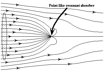
                        How can a particle absorb more energy than the light incident on it ?
                        A particle can indeed absorb more than the light incident on it. Metallic particles at ultraviolet frequencies are one class of such particles, and insulating particles at infrared frequencies are another. In the former, strong absorption is associated with excitation of surfaces plasmons; in the latter it is associated with excitation of surface phonons. In both instances, the target area a particle presents to incident light can be much greater than its geometrical cross- sectional area. This is strikingly evident from the field lines of the Poynting vector in the vicinity of a small sphere illuminated bya plane wave.

                        "Light absorption by a dipole" H. Paul and R. Fischer. Sov.Phys.Usp.26(10), Oct. 1983.
                        "In semiclassical radiation theory, the electric dipole moment induced on an atom by a strong incident field, absorbs much more energy, per sec, than is flowing through its geometrical cross section. This means, the atom has the capability to "suck up" ectromagnetic energy from a spatial region, that is by far larger than its own volume. An intuitive understanding of the effect is provided by studying, in the framework of classical electrodynamics, the energy flow in the total field made up by superposition of the incident wave and the field that is generated by the dipole also in the absorptive case."


                        Active antenna
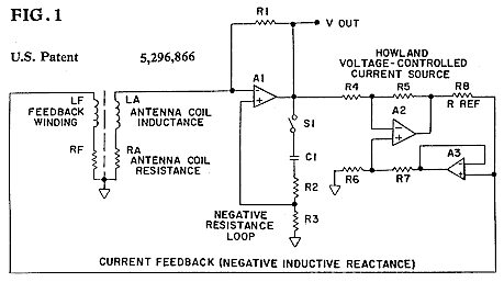
                        An antenna, which may be a search coil, connected to an active circuit which provides negative impedances, each of which is of the order of magnitude of the positive impedances which characterize this active antenna. In one embodiment, one coil terminal is connected to an amplifier which drives a voltage-controlled current source that, in turn, drives a feedback coil which is coupled to the original search coil. In another embodiment that additionally exhibits an advantageous signal-to-noise characteristic, both terminals of the search coil are connected to a differential amplifier that, in turn, provides the control voltage for a current source, which, as in the first embodiment, drives the feedback winding. The feedback coil is wound to provide positive feedback by additive superposition of both coil fields. The positive feedback provided by the feedback current lowers the antenna impedance which, in turn, increases the effective area of the antenna. This circuit configuration incorporates a differentiation inherent in the fundamental characteristic of a coil, which is sensitive to the rate-of-change of the magnetic field. The outstanding stability of this active antenna may be attributed to the inherent accuracy of this differentiation performed by the antenna coil, to the particular circuit configurations and to the particular form of feedback employed.

                        Natural Radio Receiver
                        The Very Low Frequency (VLF) band is located in the frequency range between 3KHz and 30KHz. This band has the unique characteristic of having a portion fall within the audio frequency range of our …
                        Attached Files

                        Comment


                        • #72
                          this transmitter is working.
                          The circuit with the 741 is only to keep the signal at a constant amplitude,
                          if we put a voltage stabilizer, it does the same thing. I also tried the 2N4427.
                          At these frequencies, it is a luxury because it is more expensive and is not for this job.
                          For the crystal, I had a 429 KHz. So we choose with the 150PF output capacitor which
                          frequency we will tune to, e.g. 429, 858, 1287...KHz.I tried different coils at the output,
                          with different results. When tuned, depending on the coil, the alternating voltage at the
                          antenna is from 60-300 Volts. In L2A, I put a 68μH inductance.
                          To tune the transmitter, I used an oscilloscope and a spectrum analyzer, the oscilloscope is essential.
                          Attached Files
                          Last edited by Xtrem; 07-09-2025, 01:12 PM. Reason: edit

                          Comment


                          • #73
                            Кαλωσορίζουμε Xtrem

                            η πρότασή μου είναι να κάνω μεταβλητή ισχύ εξόδου με χειροκίνητο συντονισμό όπως...


                            μην ξεχνάς δοκιμαστικό έδαφος!
                            Attached Files

                            Comment


                            • #74
                              The Power is micrometrically adjusted by the Rb,operating voltage of the oscillator, but it is not correct to change the operating voltage of a final stage.as it does in the original schematic with the 741 and the BD675 power transistor. e.g. in an audio amplifier we do not change the supply voltage of the final stage to increase or decrease the volume of the sound, but we increase or decrease the input signal.The same applies here.so the best and easiest way is to replace the R24A with a 2k trimmer.


                              what do you mean by..""μην ξεχνάς δοκιμαστικό έδαφος! ""
                              do you mean how will we test the machine in the ground?
                              I will build the receiver and then we will test it out in the field, I also see a serious design error in the receiver, which does not raise any doubts from an electronic point of view, now, if it works like a LRL, I do not know that.
                              Attached Files
                              Last edited by Xtrem; 07-10-2025, 06:28 AM. Reason: edit

                              Comment


                              • #75
                                Hi Xtrem

                                This is traditional DC power source with LM317 regulator. It precisely stabilizes Iout = Vadj /Rs,forcing the output voltage at the OUT to be Vadj =1.25V positive voltage at the adj pin. In normal situation OUT current is much higher than the Iadj bias current, with a typical value of Iadj =50uA-100uA. This allowing to ignore the Iadj bias current, without harming accuracy. Iout current is linearly programmed by changing the Rs resistance. The reason why is to control output Тх power and don't oversaturate input stage of Rx. With weak Tx out you couldn't catch the phenomenon. The goal is to find preciselly one treshold point of Rx input stage to trigger peak detector, at very tiny signal at the input which is usually in nV and uV ranges. The complete task of Rx is to dig-up the nano signals from the background noise floor.
                                ---------------------------------------------------------------
                                Yes. I do ask you how you would test a machine at test polygon? You can test your Tx with Alonso PD Rx stage, which is very sensitive. And you should shield your whole Tx cascade with metalic case and ground it. Also use double PCB with the upper side as a ground sink - as normaly done in Rf stages. This allow you to prevent many problems. I suggest you to try Rx stage from the schematic Русские Рамки without ionic-chamber. https://www.longrangelocators.com/fo...reply&p=163888
                                ---------------------------------------------------------------
                                (LM317)Iout = Vadj /Rs + Iadj Vadj /Rs = 1.25/Rs.
                                Attached Files

                                Comment

                                Working...
                                X