Announcement

Collapse
No announcement yet.

Lrl from Italy

Collapse
X
 
  • Filter
  • Time
  • Show
Clear All
new posts

  • Originally posted by FrancoItaly View Post
    In my first lrl (self oscillating) the lower strips are not needed, in fact the lower screen is used to prevent self-oscillations. I advise against using this version, I made the version with oscillator just to make the lrl less critical to build. One way to trigger the self oscillation is to use a lower strip to connect the collector of TR2 with the base of TR1 or between the collector of TR3 with the base of TR2 via an appropriate (small value) capacitor. In this way two points out of phase of 360 degrees are connected. The only possible advantage of this version is that with it you are sure to have obtained the maximum amplification. As I said in the past this lrl derives from a bug detector that auto oscillated providing a stable signal capable of revealing the "phenomenon".

    Thank you so much Mr. Franco
    Do you mean this
    Discover the magic of the internet at Imgur, a community powered entertainment destination. Lift your spirits with funny jokes, trending memes, entertaining gifs, inspiring stories, viral videos, and so much more from users.


    "use a lower strip to connect the collector of TR2 with the base of TR1 via an appropriate (small value) capacitor"
    The god of more than enough.

    Comment


    • Originally posted by taher5739 View Post
      Thank you so much Mr. Franco
      Do you mean this
      Discover the magic of the internet at Imgur, a community powered entertainment destination. Lift your spirits with funny jokes, trending memes, entertaining gifs, inspiring stories, viral videos, and so much more from users.


      "use a lower strip to connect the collector of TR2 with the base of TR1 via an appropriate (small value) capacitor"
      Yes.

      Comment


      • Originally posted by FrancoItaly View Post
        Yes.
        Hi

        I already built the original version of the LRL. The critical tests concerning voltages, touch ...
        work well.
        Is it necessary to impose the modifications like amplification.
        Thanks
        Ali

        Comment


        • Originally posted by alisuri View Post
          Hi

          I already built the original version of the LRL. The critical tests concerning voltages, touch ...
          work well.
          Is it necessary to impose the modifications like amplification.
          Thanks
          Ali
          In previous posts I suggested increasing R2 (from 220K to 560K) and decreasing R1 (from 150K to 56k) to increase the gain. Furthermore, to make P1 adjustment easier, 2 resistors (22K), one on the + 12V side and the other on the ground side should be placed in series with P1. The exact values of the 2 resistances must be found experimentally because it depends on the output value of the sensor stage (connected to the + input). If you increase the value of a resistance, you must also decrease the value of the other, so that their sum is in the range 30 - 50K. The ideal value is when P1 is set to maximum to the right, the first LED lights up and the buzzer sounds.
          Attached Files

          Comment


          • Originally posted by FrancoItaly View Post
            In previous posts I suggested increasing R2 (from 220K to 560K) and decreasing R1 (from 150K to 56k) to increase the gain. Furthermore, to make P1 adjustment easier, 2 resistors (22K), one on the + 12V side and the other on the ground side should be placed in series with P1. The exact values of the 2 resistances must be found experimentally because it depends on the output value of the sensor stage (connected to the + input). If you increase the value of a resistance, you must also decrease the value of the other, so that their sum is in the range 30 - 50K. The ideal value is when P1 is set to maximum to the right, the first LED lights up and the buzzer sounds.
            Thank you very much for the suggestions.
            Ciao

            Comment


            • pcb with antenna amplifier

              Complete pcb with antenna amplifier
              You can assemble one coil or two coils
              I assembled, Sense is better
              Attached Files

              Comment


              • Good job, I advise you to mount the sensor stage first and calibrate it and then mount the rest.

                Comment


                • Originally posted by zakari View Post
                  thank you very much sir franco
                  سلام
                  بدون خداحافظی نمیرفتین
                  بنده فقط ای دی شما رو اد کردم و به همین خاطر شماره من برای شما نمایش داده شده پس احتیاجی به نگران شدن شما نیست
                  ممنون از همکاریتون

                  Comment


                  • Originally posted by hoshi View Post
                    سلام
                    بدون خداحافظی نمیرفتین
                    بنده فقط ای دی شما رو اد کردم و به همین خاطر شماره من برای شما نمایش داده شده پس احتیاجی به نگران شدن شما نیست
                    ممنون از همکاریتون
                    Please read the forum rules -> Basic Rules of the Forums
                    and make your posts in English.

                    Comment


                    • Hello
                      Sorry I wanted to send a private message to this user.
                      After that I did everything I could not clear this text.

                      Comment


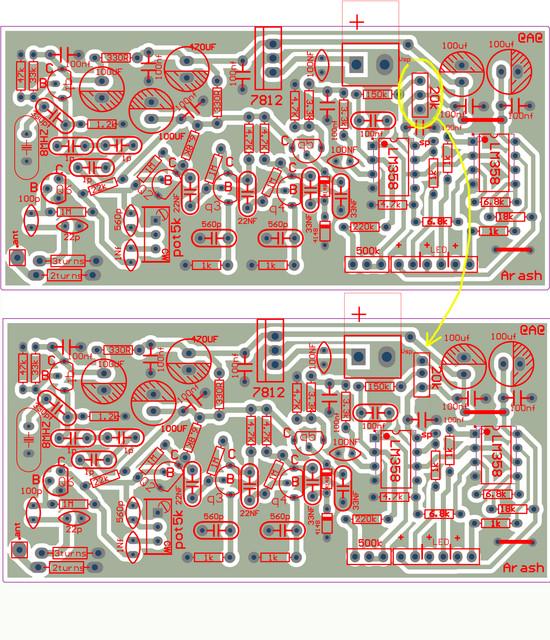
                      • I 've got a problem with the final version of 8MHz Franco's LRL build by Arash.
                        I've found a route (part) mistake in LM358 port, that's ok, working perfectly now but my main problem is that the TR5 (Q5 in current pcb) output is 3.15v no matter what i do, with crystal on or not.
                        I've double checked everything. Resistors, capacitors, nothing.

                        I upload the part that is wrong in pcb for anyone who made it


                        Any idea ?

                        Comment


                        • OK I found the fault, the silk screen in Arash PCB shows reversed every transistor image but marked correctly in pins -> EBC not CBE. I reversed them and now it's working as it should be.

                          Comment


                          • pcb

                            The pcb tested, and making a lot, is fine and works well
                            Volume is okay, wires need to be properly connected, design is for the volume multi turn, you will replace the wire for the normal volume
                            It is better for you to read the content written by Mr. Franco

                            Comment


                            • Mr. Franco and friends.
                              Everything works perfectly when antenna is directly to base of TR2, it senses electrical signals, compass effect (maybe 99% ) but then, when I connect the antenna to the amplifier makes the detector not working at all (always outputs constant max signal and no effect no matter what) like it overdrives everything. Any clues?

                              Comment


                              • Originally posted by havoc88 View Post
                                Mr. Franco and friends.
                                Everything works perfectly when antenna is directly to base of TR2, it senses electrical signals, compass effect (maybe 99% ) but then, when I connect the antenna to the amplifier makes the detector not working at all (always outputs constant max signal and no effect no matter what) like it overdrives everything. Any clues?
                                The potentiometer must be adjusted for maximum sensitivity, which often does not coincide with maximum amplification. Too much amplification can cause self oscillation.

                                Comment

                                Working...
                                X