

 Tweet
Tweet
Originally posted by Inna
View Post
-
In the original version there was only one potentiometer for threshold adjustment, later I added another one, so one is for fine tuning and the other for coarse tuning. You operate in the same way as a metal detector, adjust the gain, if any, for a stable threshold and then adjust the threshold, just below the point where the first LED lights up. -
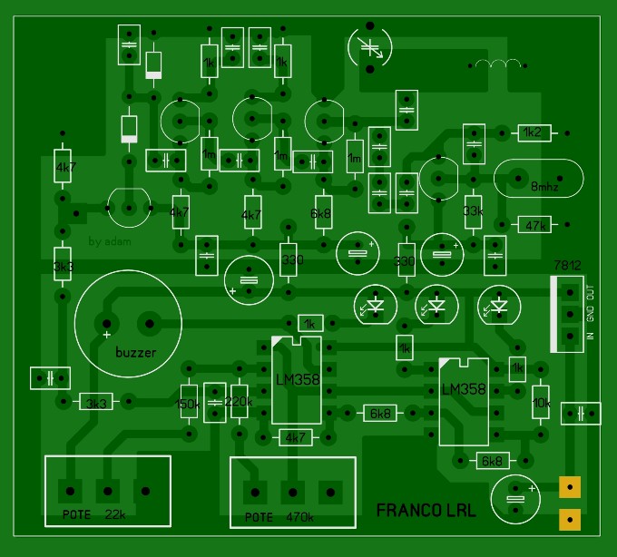
Found this diagram on a site and it looks nice
Comment
-
Very good, the antenna amplifier and the battery monitor are missing, but that's not a problem. Could you kindly share the site from which to download the files, also to have the right sizes of the pcb.Originally posted by omar View Post
Thank you.Comment
-
Thank you, it will be very useful for many forum members.Originally posted by Inna View PostComment
-
Does the last pcb version also include a variable condensator on the antenna input? This could be a good chance?Comment
-
A variable condenser on the antenna input can be useful in the 20Mhz version where a 20Mhz crystal is used and the antenna circuit is tuned on a harmonic of the oscillator, it can be 80 or 100Mhz. With 8Mhz quartz the harmonics have too small amplitude. However, with the 8 Mhz version, you can try to adjust the capacitor to look for a point where the DC output signal increases, possibly putting a 22pF capacitor in parallel with the variable capacitor.Originally posted by Inna View PostComment
-
-
-
-
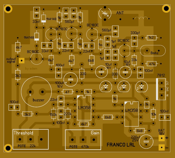
Sorry again, but on this pcb posted by Omar, I can't find the solder point for the antenna. Capacitor values are not written. With a little patience they can be deduced, even if at sight, they seem much more than those in the original scheme. Instead in the point that I highlighted with an orange circle, I can't figure out what should be connected to it.Attached FilesComment
-
-
Dear, the point you marked with a circle. It is the measuring point of the sensor output.
I will use my friend to write down the missing valuesComment
-
Antenna point..
Thanks Omar, please could you ask even where is the antenna point?Originally posted by omar View PostComment
-
Comment
-
Comment