Announcement

Collapse
No announcement yet.

Lrl from Italy

Collapse
X
 
  • Filter
  • Time
  • Show
Clear All
new posts

  • Originally posted by Inna View Post
    Yes, I wrote wrong, I meant 100/220 kohm. You have to excuse me, but I'm just an electronics hobbyist, so P2 adjusts the gain which, once adjusted, always remains the same, so it's possible not to take it out of the box and replace it with an internal trimmer. Then If I may ask again, what do the other 2 potentiometers regulate? To be clearer, Mr. Franco, I ask you, could you describe what to do with the device and how to adjust it for research, after turning it on? That is, on which potentiometers to intervene and how to start field research? In short, having a small user manual on plein-air...
    Thanks for your patience.
    In the original version there was only one potentiometer for threshold adjustment, later I added another one, so one is for fine tuning and the other for coarse tuning. You operate in the same way as a metal detector, adjust the gain, if any, for a stable threshold and then adjust the threshold, just below the point where the first LED lights up.

    Comment


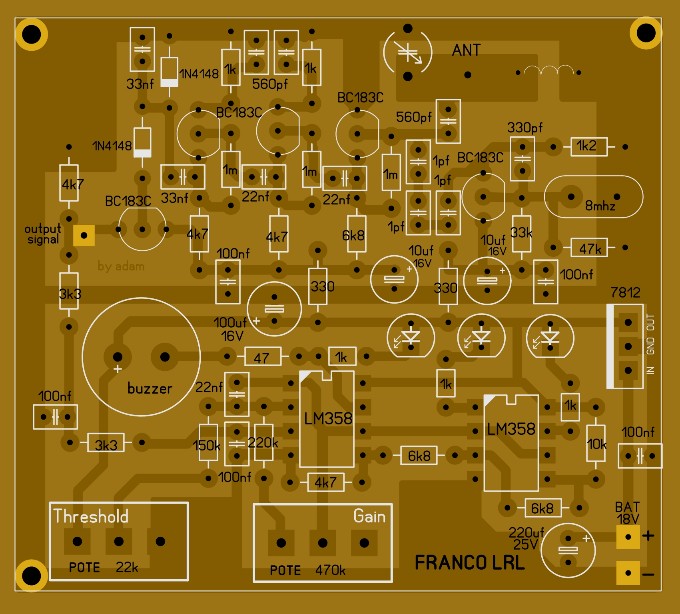
    • Found this diagram on a site and it looks nice

      Comment


      • Originally posted by omar View Post
        Found this diagram on a site and it looks nice


        Very good, the antenna amplifier and the battery monitor are missing, but that's not a problem. Could you kindly share the site from which to download the files, also to have the right sizes of the pcb.
        Thank you.

        Comment


        • Originally posted by Inna View Post
          Very good, the antenna amplifier and the battery monitor are missing, but that's not a problem. Could you kindly share the site from which to download the files, also to have the right sizes of the pcb.
          Thank you.
          Thank you, it will be very useful for many forum members.

          Comment


          • Does the last pcb version also include a variable condensator on the antenna input? This could be a good chance?

            Comment


            • https://top4top.io/downloadf-2530spk8i0-rar.html

              Comment


              • Originally posted by Inna View Post
                Does the last pcb version also include a variable condensator on the antenna input? This could be a good chance?
                A variable condenser on the antenna input can be useful in the 20Mhz version where a 20Mhz crystal is used and the antenna circuit is tuned on a harmonic of the oscillator, it can be 80 or 100Mhz. With 8Mhz quartz the harmonics have too small amplitude. However, with the 8 Mhz version, you can try to adjust the capacitor to look for a point where the DC output signal increases, possibly putting a 22pF capacitor in parallel with the variable capacitor.

                Comment


                • Originally posted by FrancoItaly View Post
                  A variable condenser on the antenna input can be useful in the 20Mhz version where a 20Mhz crystal is used and the antenna circuit is tuned on a harmonic of the oscillator, it can be 80 or 100Mhz. With 8Mhz quartz the harmonics have too small amplitude. However, with the 8 Mhz version, you can try to adjust the capacitor to look for a point where the DC output signal increases, possibly putting a 22pF capacitor in parallel with the variable capacitor.
                  A variable capacitor like these?
                  Attached Files

                  Comment


                  • Originally posted by Inna View Post
                    A variable capacitor like these?
                    Yes, 50pF is ok.

                    Comment


                    • Originally posted by FrancoItaly View Post
                      Yes, 50pF is ok.
                      Thanks! Always there to help. Great Mr. Franco.

                      Comment


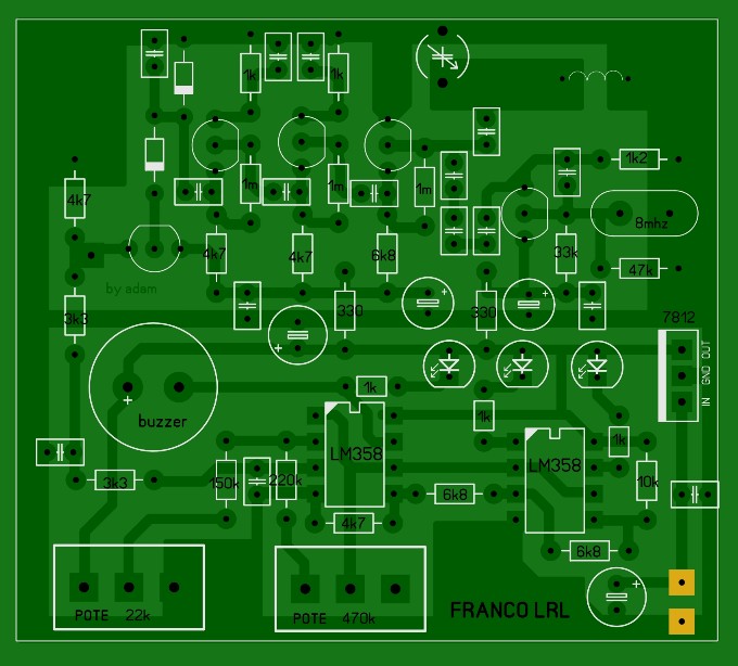
                      • Sorry again, but on this pcb posted by Omar, I can't find the solder point for the antenna. Capacitor values ​​are not written. With a little patience they can be deduced, even if at sight, they seem much more than those in the original scheme. Instead in the point that I highlighted with an orange circle, I can't figure out what should be connected to it.
                        Attached Files

                        Comment


                        • Dear, the point you marked with a circle. It is the measuring point of the sensor output.

                          I will use my friend to write down the missing values

                          Comment


                          • Antenna point..

                            Originally posted by omar View Post
                            Dear, the point you marked with a circle. It is the measuring point of the sensor output.

                            I will use my friend to write down the missing values
                            Thanks Omar, please could you ask even where is the antenna point?

                            Comment


                            • Comment


                              • Originally posted by omar View Post
                                Great! Well done Omar!

                                Comment

                                Working...
                                X