Announcement

Collapse
No announcement yet.

MINEORO 2008 MODS.

Collapse
X
 
  • Filter
  • Time
  • Show
Clear All
new posts

  • 468 / 5.000
    ?eviri sonu?ları
    ?eviri sonucu
    Yes T?rkiye

    First, plug an ordinary RX into your IR receiver. Does this inform the output of the RX circuit? Test it using a TV remote. I don't think there will be a problem with the general sensor. But there should be no minus at the output of the 1m drain you mentioned. and there should be no short circuits to other wires entering the overall sensor.

    Don't worry about frequencies for now, focus on replacing all faulty parts.

    Transistors connected directly to minus have a high risk of failure (legs C).
    Comment


    • Hi everyone
      Look at the photo.
      Does anyone have the electric field amplifier circuit diagram?
      Attached Files

      Comment


      • Originally posted by aft_72005 View Post
        Hi everyone
        Look at the photo.
        Does anyone have the electric field amplifier circuit diagram?
        I tested with LM 324, only one problem occurs. The device works, but when it starts working, the horn that confirms the balance does not sound. I think it is not LM 324.

        Comment


        • Originally posted by Yusufyaba View Post
          468 / 5.000
          ?eviri sonu?ları
          ?eviri sonucu
          Yes T?rkiye

          First, plug an ordinary RX into your IR receiver. Does this inform the output of the RX circuit? Test it using a TV remote. I don't think there will be a problem with the general sensor. But there should be no minus at the output of the 1m drain you mentioned. and there should be no short circuits to other wires entering the overall sensor.

          Don't worry about frequencies for now, focus on replacing all faulty parts.

          Transistors connected directly to minus have a high risk of failure (legs C).
          I have already tested with a normal sub IR receiver, it is clear inside the photo. It senses the TV control from a distance of 40 cm.But this distance should be more than 40 cm.

          Comment


          • Originally posted by ishtar hunter View Post
            I have already tested with a normal sub IR receiver, it is clear inside the photo. It senses the TV control from a distance of 40 cm.But this distance should be more than 40 cm.
            468 / 5.000
            ?eviri sonu?ları
            ?eviri sonucu
            Yes T?rkiye
            Merhaba abi ş? yazdiklarinizi anayamadim . neyi kast ediyorsunuz bilamadim. Bana IR alicinin bilğisi lazim . Teşakurler.

            Comment


            • Originally posted by aft_72005 View Post
              Hi everyone
              Look at the photo.
              Does anyone have the electric field amplifier circuit diagram?
              Give me some time, I will draw the whole schematic of this device from the main circuit.

              Comment


              • Originally posted by ishtar hunter View Post
                Give me some time, I will draw the whole schematic of this device from the main circuit.
                Hi ishtar hunter

                OK .. no problem .. i waiting ... and thank you for all the trouble you have taken in the matter .

                my email aft72005.1@gmail.com

                Comment


                • Originally posted by ishtar hunter View Post
                  I tested with LM 324, only one problem occurs. The device works, but when it starts working, the horn that confirms the balance does not sound. I think it is not LM 324.
                  also i don't know ... lm324 how can be electric field detector and TX coil stimulator ..
                  if you reverse engineering this section ... then from circuit we can understand how it works .

                  Comment


                  • Originally posted by ishtar hunter View Post
                    Give me some time, I will draw the whole schematic of this device from the main circuit.
                    lm324 included 4 op amp ... one of them need for TX oscillation.. 3 remain may be them electric filed amplifier and filter 50 HZ

                    Comment


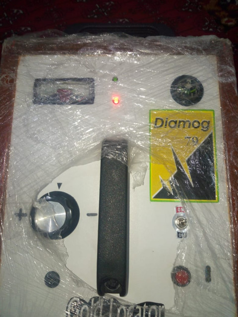
                    • DIAMOG-79 LONG RANGE GOLD LOCATOR

                      Please check the following YouTube link for DIAMOG-79 Performance and stability of the device.

                      https://www.youtube.com/@DIAMOG-79./videos

                      Comment


                      • Comment


                        • Comment


                          • DIAMOG-79 LONG RANGE GOLD LOCATOR

                            Comment


                            • Originally posted by aft_72005 View Post
                              Hi everyone
                              Look at the photo.
                              Does anyone have the electric field amplifier circuit diagram?
                              It's not electric field detector , it's magnetometer , you found only the true here

                              Comment


                              • i don't think FG90 is the best LRL , if you understand the LRL SECRETS, you can build better

                                Comment

                                Working...
                                X